Generate Code to Manually Deploy a ROS Node from Simulink
This example shows you how to generate C++ code from a Simulink® model to deploy as a standalone ROS node. The code is generated on your computer and must be manually transferred to the target ROS device. No connection to the hardware is necessary for generated the code. For an automated deployment of a ROS node, see Generate Standalone ROS Node from Simulink.
Prerequisites
This example requires Simulink Coder™ and Embedded Coder®.
A Ubuntu® Linux® system with ROS is necessary for building and running the generated C++ code. You can use your own Ubuntu ROS system, or you can use the Linux virtual machine used for ROS Toolbox examples. See Get Started with Gazebo and Simulated TurtleBot for instructions on how to install and use the virtual machine.
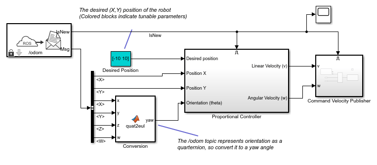
Review the Feedback Control of a ROS-Enabled Robot example, which details the Simulink model that the code is being generated from.
Configure a Model for Code Generation
Configure a model to generate C++ code for a standalone ROS node using the Configuration Parameters. The model used here is the proportional controller introduced in the Feedback Control of a ROS-Enabled Robot example.
Open the proportional controller model.
open_system('robotROSFeedbackControlExample')Copy the entire model to a new blank Simulink model.
Delete the Simulation Rate Control block.
On the Apps tab, under Control Systems, click Robot Operating System (ROS).
In the Robot Operating System (ROS) dialog box that opens
up, select Robot Operating System (ROS) from the
ROS Network drop-down. This opens up the
ROS tab in the toolstrip which shows the specified ROS
Network in the Connect section.
In the Prepare section under ROS tab, click Hardware Settings to open the model configuration parameters dialog box.
The Hardware board settings section contains settings
specific to the generated ROS package, such as information included in the
package.xml file. Change Maintainer
name to ROS Example User and click
OK.
In the Solver pane of the Configuration
Parameters dialog, ensure the Type is set to
Fixed-step, the Solver is
set to ode3 (Bogacki-Shampine)and the Fixed-step
size is set to 0.05. In generated code, the
fixed-step size defines the actual time step that is used for the model update
loop. See Execution of Code Generated from a Model (Simulink Coder) for more information.
In the Code Generation pane, ensure variable-size signals is enabled.
Click OK to close the Configuration
Parameters dialog. Save the model as
RobotController.slx.
Configure the Build Options for Code Generation
After configuring the model, you must specify the build options for the target hardware and set the folder or building the generated code.
Under ROS tab, from the Deploy Type section, select the deployment type as Standard Node.
Click Deploy under the ROS tab. Then under Deployment, click Build Model. This setting ensures that code is generated for the ROS node without building it on an external ROS device.
Generate and Deploy the Code
Start a ROS master in MATLAB®. This ROS master is used by Simulink for the code generation steps.
In the MATLAB command window type:
rosinit
Set the current folder to a writable directory. This folder is the location that generate code will be stored when you build the model.
Under the C Code tab, click Generate Code or press Ctrl+B to start code generation for
the model.
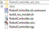
Once the build completes, two new files are written to your folder.
RobotController.tgz–– An archive containing the C++ codebuild_ros_model.sh–– A shell script for extracting and building the C++ code
Manually transfer the two files to the target machine. If you
connect to a ROS device using rosdevice, you can send files using
putFile. Otherwise, this step
assumes you are using the Linux virtual machine used for Robotics System Toolbox™ examples. The virtual machine is configured to accept SSH and SCP
connections. If you are using your own Linux system, consult your system administrator for a secure way to
transfer files.
Ensure your host system (the system with your
RobotController.tgz and
build_ros_model.sh files) has an SCP client. For
Windows® systems, the next step assumes that PuTTY SCP client
(pcsp.exe) is installed.
Use SCP to transfer the files to the user home director on the Linux virtual machine. Username is user and password
is password. Replace
<virtual_machine_ip> with your virtual machines IP address.
Windows host systems:
pscp.exe RobotController.tgz build_ros_model.sh user@<virtual_machine_ip>:
Linux or macOS host systems:
scp RobotController.tgz build_ros_model.sh user@<virtual_machine_ip>:
The build_ros_model.sh file is not specific to this model.
It only needs to be transferred once for multiple models.
On the Linux system, execute the following commands to create a Catkin workspace. You may use an existing Catkin workspace. Build the Catkin workspace.
mkdir -p ~/catkin_ws_simulink/src
cd ~/catkin_ws_simulink/src
catkin_init_workspace
cd ..
catkin_make
Decompress and build the node there using the following command in Linux. Replace <path_to_catkin_ws> with the path
to your catkin workspace. If the node uses custom messages, you must manually
copy the necessary custom message packages in
<path_to_catkin_ws>/msg folder before building the
node.
cd ~
./build_ros_model.sh RobotController.tgz <path_to_catkin_ws>
If that does not work, ensure that build_ros_model.sh is
set up as an executable by entering the following command.
chmod +x build_ros_model.sh
The generated source code is under
~/catkin_ws_simulink/src/robotcontroller/. Review the
contents of the package.xml file. Verify that the node
executable was created using:
file ~/catkin_ws_simulink/devel/lib/robotcontroller/robotcontroller_node
If the executable was created successfully, the command lists information about the file.
The model is now ready to be run as a standalone ROS node on your device.
Optional: You can then run the node using this command.
Replace <path_to_catkin_ws> with the path to your catkin
workspace.
~/<path_to_catkin_workspace>/devel/lib/robotcontroller/robotcontroller_node