Getting Started with UR RTDE Blocks Library to Control UR Series Cobot from Simulink
This example shows how to use Simulink blocks under UR RTDE Blocks Simulink Library to manipulate motion of UR Series cobot using joint configuration or joint space waypoints, and obtain feedback from the cobot.
The Robotics System Toolbox™ Support Package for Universal Robots UR Series Manipulators enables you to connect and control UR Series Manipulators from Universal Robots using MATLAB and Simulink®. The Simulink library, UR RTDE Blocks, includes two blocks that allow you to command the cobot using RTDE interface - either by specifying the required joint configuration (Send Joint Configuration block) or by providing the required joint waypoints (Follow Joint Waypoints block). The library also provides blocks to read joint configuration and motion status to verify the manipulation.
Prerequisites
Complete initial setup to establish communication between MATLAB® and URSim or between MATLAB® and UR Series hardware. For more information, see Set Up URSim Offline Simulator for RTDE or Set Up UR Series Cobot for RTDE.
Model
This example provides a Simulink model, gettingStartedExampleRTDEBlocks, which includes the various blocks from the UR RTDE Blocks Simulink Library, and additionally uses the two Manual Switch blocks from Simulink to enable/disable the manipulation of the cobot.
modelName = "gettingStartedExampleRTDEBlocks";
open_system(modelName);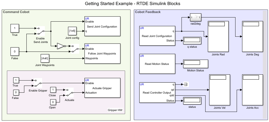
The Enable port in the two blocks, Send Joint Configuration and Follow Joint Waypoints, accepts Boolean values (0 or 1) from these Manual Switch blocks, and keeps the motion active while the value is 1.
Control Cobot Manipulation and Obtain Feedback
All the RTDE-based Simulink blocks in the model are configured with the UR Controller IP address parameter in the blocks set to 192.168.1.10 (using the variable ipAddress). Validate this IP address by completing the test connection to UR Series cobot or URSim simulator, by first completing the Hardware Setup process. To change the IP address, if required, set the new IP address using the Set UR Controller IP parameter in the model.
After that, you can proceed with these steps to control the cobot using the Simulink model:
Click Run to simulate the model.
Double-click the Enable Send Joints (Manual Switch) block to toggle the switch position to accept 1 (True), thereby enabling the Send Joint Configuration block. This results in the actual movement of cobot's joints as per the values defined for Joint Config (Constant) block connected to the q input of the block.
Observe the output value of Read Motion Status block. The Motion Status (Display) block displays one of these values : 2 (if the motion is completed), 1 (if the motion execution is in progress), or 0 (if the motion has not started).
Once the Motion Status (Display) block displays 2, verify the final position of joints by observing the values for Joints Rad or Joints Deg (Display) blocks connected to the q output of Read Joint Configuration block.
Double-click the Enable Send Joints (Manual Switch) block to toggle the switch position to accept 0 (False), thereby enabling the Follow Joint Waypoints block and disabling the Send Joint Configuration block . This results in the actual movement of cobot's joints as per the values defined for Joint Waypoints (Constant) block connected to the Waypoints input of the Follow Joint Waypoints block.
Once the Motion Status (Display) block displays 2, verify the movement of joints by observing the values for Joints Vel or Joints Acc (Display) blocks connected to the qd and qdd outputs respectively of the Read Controller Output block.
Double-click the Enable Gripper (Manual Switch) block to toggle the switch position to accept 1 (True), thereby enabling the Actuate Gripper block. Double-click the Actuate (Manual Switch) block to toggle the switch position to accept 1 (True). This results in the closing the gripper connected to the cobot's end-effector.
Generate Code and Deploy to Target
The Simulink blocks in UR RTDE Blocks Simulink Library support C/C++ code generation using Simulink Coder™. You can deploy the generated code to platform-specific targets like Windows® or Linux® host with a connected UR Series cobot or URSim simulator, or to a Raspberry Pi® target.
Communicate with Target Using XCP-Based Simulation
This example provides a script that applies the required settings for the various Simulink Configuration Parameters, which enable the Simulink model to perform the Monitor and Tune (External mode) operation from a Windows® host computer. After enabling Monitor and Tune (which uses XCP on TCP/IP), when you toggle the switch positions in the model, the required joint configurations or joint waypoints of the cobot are communicated to the target hardware immediately.
Open the Simulink model,
gettingStartedExampleRTDEBlocks.Run the script:
configureRTDEForHost('gettingStartedExampleRTDEBlocks')to apply the required settings for the Simulink model to communicate with UR Series cobot (either physical hardware or URSim Offline Simulator) over External mode. If you want to communicate with a Raspberry Pi board instead, you can set the Hardware board parameter to the specific Raspberry Pi board, while leaving the other settings configured using configureRTDEForHost.To start simulation, on the Hardware tab of the Simulink model, click Monitor & Tune. Adjust the position of Manual Switch blocks in the model or change other values, and observe the movement of cobot's joints in real-time.
To stop the simulation, on the Hardware tab, click Stop. Otherwise, if the simulation Stop Time parameter is set to a specific number of seconds, Monitor and Tune stops when that time elapses.
Deploy Model to Target
If you are satisfied with the behavior of the cobot while performing the Monitor and Tune operation, you can proceed to deploy the model to the target. With Simulink Coder™, you can generate code for your Simulink model and deploy it to run as a standalone application on the target. This application continues to run even if the hardware is disconnected from your development computer. To do this, on the Hardware tab of the Simulink model, click Build, Deploy & Start.
Other Things to Try
Use a supervisory controller using Stateflow® to send Boolean values to the various Manual Switch blocks.
The present example uses a constant value for Joint Configuration and Joint Waypoints input. Try to implement dynamic calculation of required joint configuration and joint waypoints based on desired end-effector pose.