Path Editing
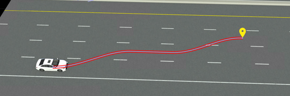
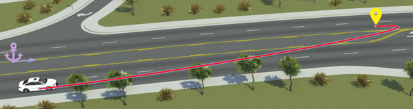
During simulation, actors in a scenario move using either their built-in behavior or by moving along a path that you specify for them. This scenario shows a sample path for a vehicle that includes segments following the road and one segment that goes off-road.
Add Path Along Driving Lane
To add a path for an actor along its driving lane, follow these steps:
In the scenario editing canvas, click an actor to select it.
Right-click along the driving lane of the actor.
The added path segment extends from the actor to the point where you right-clicked and ends with a path waypoint.
By default, paths added onto a road network snap to the center of the lane. You can then extend this path by clicking and dragging the waypoint, and the path remains snapped to the lane center.
Create Lane Changes
To add a lane change to a path, drag a waypoint into another lane.
You can drag waypoints across multiple lanes.
The generated path remain snapped to the lane centers. By default, lane changes take place over a maximum distance of 20 meters. To modify this distance, select the path or any segment or waypoint along it, and in the Attributes pane, modify the Lane Change Distance attribute. Lane change distances apply to the entire path. This table shows sample lane change distance values.
| Lane Change Distance = 10 meters | Lane Change Distance = 20 meters | Lane Change Distance = 30 meters |
|---|---|---|
|
|
|
|


Extend Path with Additional Segments
To extend paths by adding new path segments, follow these steps:
Click the path you want to extend. Alternatively, click a segment or waypoint along that path.
Right-click the location that you want to extend the path to.
A new path segment extends from the previous waypoint and ends in a new waypoint at the point where you right-clicked.
Split Path into Separate Segments
To split a path or path segment into separate segments, right-click within the path to add a new waypoint.
Modify Path Tangents
To change the shapes of paths, you can modify the tangents of path waypoints. To modify path tangent, click a waypoint to select it, and then click and drag the tangent lines to set the direction and scale of the tangent.
For more details on working with tangents, see Tangent Editing.
Set Specific Path Lengths
To set specific lengths of path segments, select a path waypoint and in the Attributes pane, under Forward Offset, modify the Offset value. This value sets how many meters the waypoint is offset from its parent anchor.
By default, path segments are anchored to the road. If you want to set path lengths relative to the vehicle, then you must change the anchor parent of the waypoints.
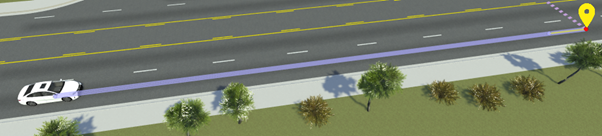
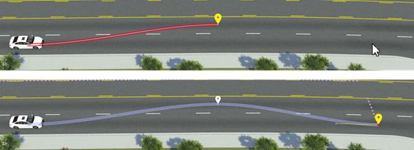
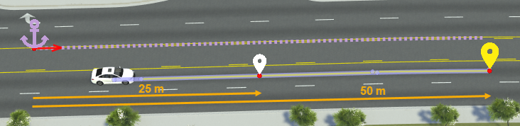
Consider this vehicle path containing two path waypoints. The waypoints are 25 meters and 50 meters in front of the road anchor, respectively.
Suppose you want to set the intermediate waypoint 10 meters in front of the vehicle. Changing only the Offset value of this waypoint offsets it from the road anchor, not the vehicle.
To offset the waypoint 10 meters from the vehicle, you must first change its anchor parent from the road anchor to the vehicle, and then set the offset value, by following these steps:
Select the waypoint.
From the Attributes pane, select the name of the parent anchor from the Anchor attribute box.
Select the vehicle from either the scenario editing canvas or the Logic editor. RoadRunner outlines these areas in blue lines.
Set Offset to
10meters.
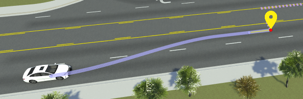
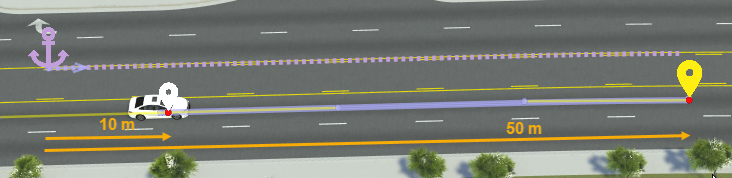
This image shows the updated offset values. If you drag the vehicle, the first waypoint remains fixed 10 meters in front of the vehicle. The second waypoint remains fixed in place, because it is still anchored to the road. If you wanted the second waypoint to remain fixed 50 meters in front of the vehicle, you must change its anchor parent to the vehicle as well.

For more details on working with anchors, see Scenario Anchoring System.
Set Precise Waypoint Locations
By default, path waypoints lock to an anchor. If you disable anchoring, you can set more precise (x,y,z) locations of path waypoints. Follow these steps:
In the scenario editing canvas, select the path waypoint you want to set the precise location for.
In the Attributes pane, under Point Offsets, clear the Enable Anchoring attribute.
Under Position, modify the X, Y, and Z coordinate values. These values are relative to the scene origin.
Shift Paths Within Lanes
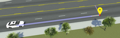
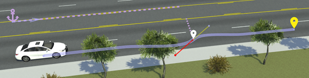
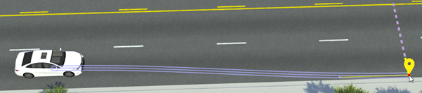
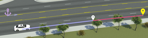
To shift a path laterally within a lane, hold the Ctrl key and then drag the path waypoint you want to shift. This image shows a path segment shifted to the curb to simulate a parking maneuver.
To set more precise lane-relative locations of waypoints, modify the waypoint attributes in the Lane Offset section of the Attributes pane. This table shows sample lane offset attributes for a waypoint.
| Lane Offset Attributes | Description |
|---|---|
Relative To — Offset From
— Direction —
Travel
Direction — Lateral
Offset — | Set waypoint two lanes from the road edge and in the same travel direction of the road anchor. Offset the lane 1.5 meters to the right of the lane center.
|
Create Free-Form Paths
All path segments so far have followed the road network. To create more free-form paths that go on and off the roads, you can have path segments ignore the road network.
Click a path segment to select it.
In the Attributes pane, select Freeform under Route Segment Parameters.
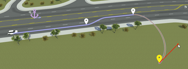
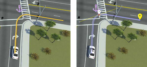
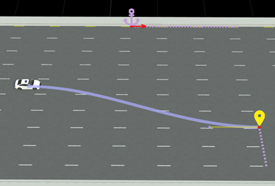
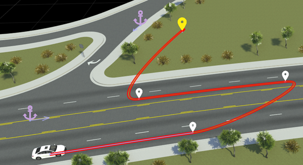
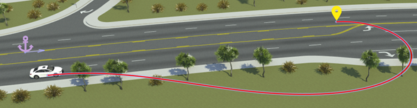
When you drag the waypoint at the end of the segment that ignores the road network, the segment no longer snaps to the center of the lane. You can now more easily create U-turn or off-road paths. For example, in this image, the second and fourth path segments ignore the road network.
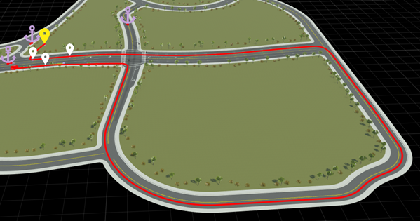
If you modify these segments to follow the road network, then they follow the road to reach the desired waypoints, leading to long and winding paths. For example, this image shows the second path segment following the road network. To reach the opposite side of the highway, the segment follows the long loop around the intersection.
For additional control over segments that ignore the road network, you modify their curve types. In the Attributes pane, change the Curve Type attribute of the selected segments. This table describes the curve types.
| Curve Type | Description |
|---|---|
| Cubic (default) | Path segment follows a cubic polynomial curve.
|
| Clothoid | Path segment follows a clothoid curve, where the curve changes linearly with distance.
|
Export Options for Paths
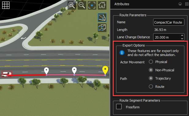
When exporting a path to the ASAM OpenSCENARIO® format, you can configure these export options. First, select a path segment, and then, in the Attributes pane, in the Export Options section, specify these options:
Actor Movement — Export the motion of a vehicle as
PhysicalorNon-Physical(default).Physicalmovement instructs the simulator to consider the dynamic constraints of the vehicle during simulation.Non-Physicalmovement instructs the simulator to ignore dynamic constraints of a vehicle.Path — Export the path of a vehicle as
Trajectory(default) orRoute. TheRouteoption specifies directional route information of the vehicle using a list of ordered waypoints. TheTrajectoryoption specifies a precise path of the vehicle using mathematical shapes and timing information.
For more information on these export options, see Path-Following Motion (XML) and Path-Following Motion (DSL).
Note
These Export Options affect only files exported to the ASAM OpenSCENARIO format. They do not affect the simulation in RoadRunner Scenario.