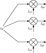
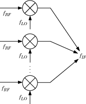
Set up an OpenIF object as a multiband receiver, add three mixers to it, and obtain information about its spur-free zones.
Define an OpenIF object. The first input is the bandwidth of the IF signal (50 MHz). The 'IFLocation','MixerOutput' name-value pair specifies a down-converting configuration.
The following figure shows the down-converting configuration.
Define the first mixer with an intermodulation table and add it to the OpenIF object. Mixer 1 has a RF center frequency at 2.4 GHz, has a RF bandwidth of 100 MHz, and uses low-side injection.
Mixer 2 has an RF center frequency at 3.7 GHz, has a bandwidth of 150 MHz, and uses low-side injection.
Mixer 3 has an RF center frequency at 5 GHz, has a bandwidth of 200 MHz, and uses low-side injection.
The multiband receiver is fully defined and ready for spur-free-zone analysis. Use the report method to analyze and display spur and spur-free zone information at the command line. The method also returns information about the mixers in the receiver.
     Intermediate Frequency (IF) Planner
     IF Location: MixerOutput

     -- MIXER 1 --
     RF Center Frequency: 2.4 GHz
     RF Bandwidth: 100 MHz
     IF Bandwidth: 50 MHz
     MixerType: low
     Intermodulation Table:   99   0  21  17  26
                              11   0  29  29  63
                              60  48  70  65  41
                              90  89  74  68  87
                              99  99  95  99  99

     -- MIXER 2 --
     RF Center Frequency: 3.7 GHz
     RF Bandwidth: 150 MHz
     IF Bandwidth: 50 MHz
     MixerType: low
     Intermodulation Table:   99   0   9  12  15
                              20   0  26  31  48
                              55  70  51  70  53
                              85  90  60  70  94
                              96  95  94  93  92

     -- MIXER 3 --
     RF Center Frequency: 5 GHz
     RF Bandwidth: 200 MHz
     IF Bandwidth: 50 MHz
     MixerType: low
     Intermodulation Table:   99   0  15  23  36
                              10   0  34  27  59
                              67  61  56  59  68
                              97  82  81  60  77
                              99  99  99  99  96

     Spur-Free Zones:
        5.00 -    6.25 MHz
        6.25 -    8.33 MHz
        8.33 -  465.00 MHz
      495.00 -  581.25 MHz
      618.75 -  720.00 MHz
      760.00 -  775.00 MHz
      825.00 -  900.00 MHz
        1.03 -    1.16 GHz
        1.28 -    1.41 GHz
        1.52 -    1.56 GHz
        1.71 -    1.76 GHz
        2.04 -    2.17 GHz
        2.27 -    2.33 GHz
        2.56 -    2.71 GHz
        3.07 -    3.12 GHz
        3.44 -    3.51 GHz
        3.83 -    3.91 GHz
        4.09 -    4.35 GHz
        5.29 -    5.43 GHz
        5.73 -    5.79 GHz
        6.81 -    6.86 GHz
        7.66 -    7.84 GHz
        8.82 -    9.05 GHz
       10.23 -   10.85 GHz
       11.35 -   11.43 GHz
       13.61 -   14.08 GHz
       15.33 -   18.10 GHz
       18.90 -   19.58 GHz
       20.43 -   21.73 GHz
       22.68 -   24.48 GHz
Use the show method to analyze the receiver and produce an interactive spur graph. Generating a spur graph is a convenient way to summarize the results of the analysis graphically.


