Deploy Ladder Diagram
Using Simulink® PLC Coder™ you can generate Structured Text, along with test bench code and import the generated code into the target IDE.
Learning Objectives
In this tutorial you will learn how to:
Open the
plcdemo_ladder_timersmodel and prepare the model for code generation. To open the model, enter:openExample('plcdemo_ladder_timers');Verify the code you generated.
Have your generated code either automatically or manually imported into your target IDE.
Prerequisites
Simulink PLC Coder
You have access to either Rockwell Automation® RSLogix™ 5000 or Studio 5000 IDE.
Workflow
Open the
plcdemo_ladder_timersmodel. To open the model, enter:openExample('plcdemo_ladder_timers');Open the model settings and set Solver Selection to
Fixed-stepand Solver todiscrete(no continuous states).
You can manually import the generated L5X file into RSLogix 5000 or Studio 5000 IDEs.
Importing Generated Ladder Diagram Code Manually
For L5X import file generation:
Right-click the
Motor Controllerblock and, in the PLC Coder app section , Generate PLC Coder row, click the
Settings button.
, Generate PLC Coder row, click the
Settings button.This displays the PLC Code Generation configuration parameters window:
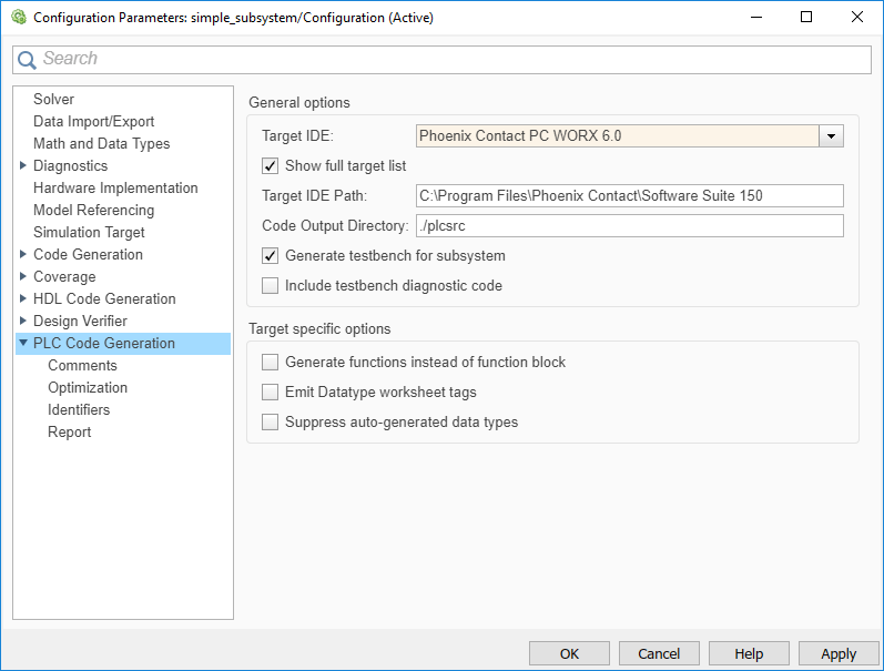
On the PLC Code Generation pane, from the Target IDE list, select either
Rockwell Studio 5000:AOIorRockwell RSLogix5000:AOI.In Target IDE Path, enter the path to the folder where you want the generated L5X file to be saved. In, Code Output Directory, enter the name of the folder to save the generated L5X file.
Click Apply.
Right-click the
Motor Controllerblock and, in the PLC Coder app section, Generate PLC Coder row, click the
Generate PLC Code button  .
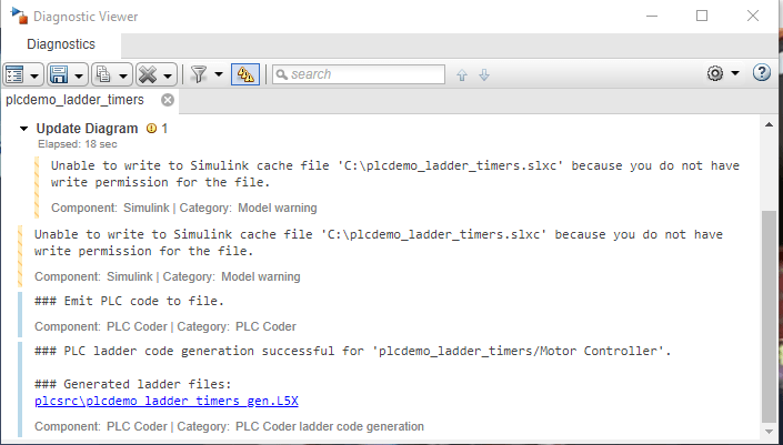
.Upon, completion of code generation the Diagnostic window displays a message with the path to the generated L5X file.