Transmitter
Amplify and transmit signal
Libraries:
Phased Array System Toolbox /
Transmitters and Receivers
Description
The Transmitter block amplifies and transmits waveform pulses. The transmitter can either maintain coherence between pulses or insert phase noise.
Examples
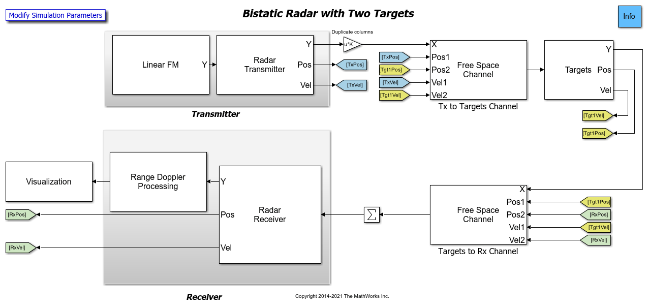
Simulating a Bistatic Radar with Two Targets
Simulate a bistatic radar system with two targets. The transmitter and the receiver of a bistatic radar are not co-located and move along different paths.
Ports
Input
Input waveform, specified as a complex-valued matrix.
The size of the first dimension of the input matrix can vary to simulate a changing signal length. A size change can occur, for example, in the case of a pulse waveform with variable pulse repetition frequency.
Data Types: double
Output
Transmitted signal, output as a complex-value matrix.
Y is the amplified input waveform where the
amplification is based on the characteristics of the transmitter, such
as the peak power and the gain.
Data Types: double
Transmitter on-off status, output as a 0 or 1. A 1 indicates that the transmitter is on, and a 0 indicates that the transmitter is off.
Dependencies
To enable this port, select the Enable transmitter status output check box.
Data Types: double
Phase noise, output as a scalar.
Dependencies
To enable this port, select the Enable pulse phase noise output check box.
Data Types: double
Parameters
Main
Peak power, specified as a positive scalar. Units are in Watts.
Data Types: single | double
Method for applying gain to the transmitted signal, specified as
Linear, Cubic
polynomial or Lookup table.
When set to
Linear, linear gain is applied.When set to
Cubic polynomial, a cubic polynomial model is used to apply non-linear gain.When set to
Lookup table, a lookup table is defined to directly specify output power and phase shift as a function of input power.
Data Types: char | string
Linear transmitter gain, specified as a real scalar or length-N vector of real values. N is the number of channels. If the Gain (dB) parameter is a scalar, the same value is applied to all channels. Units are in dB.
Dependencies
To enable this property, set the Gain method
parameter to Linear or Cubic
polynomial.
Data Types: single | double
Output IP3, specified as a scalar or length-N vector of real values. N is the number of channels. OIP3 expresses the non-linearity of the transmitter or receiver. OIP is also called the third-order intercept point. If OIP3 is a scalar, the same value is applied to all channels. See Nonlinearities and Noise in Idealized Baseband Amplifier Block (RF Blockset) for a detailed discussion of OIP3. Units are in dBm.
Dependencies
To enable this property, set the Gain method
parameter to Cubic polynomial.
Data Types: single | double
AM/AM-AM/PM lookup table, specified as a 3-by-M-by-N real-valued array. The lookup table specifies amplifier power characteristics. M is the number of table entries and N is the number of channels. Each row in the table expresses the relationship between output power or phase change as a function of input power. Specify AM/AM (in dB/dB) and AM/PM (in deg/dB) characteristics in a [Pin(dBm),Pout(dBm),Phase shift(degrees)]-by-M matrix or [Pin(dBm),Pout(dBm),Phase shift(degrees)]-by-M-by-N array. Use the table to linear interpolate or extrapolate power values. The column 1 input power must increase monotonically. There must be at least 3 rows in the table. The power output can be written as:
Dependencies
To enable this property, set the Gain method
parameter to Lookup table.
Data Types: single | double
Transmit loss factor, specified as a nonnegative scalar or length-N vector of nonnegative values. N is the number of channels. If Loss factor (dB) parameter is a scalar, the same value is applied to all channels.
Dependencies
To enable this property, set the Gain method
parameter to Linear.
Data Types: double | single
Select this check box to output the transmitter-in-use status for each output sample from the output port TR.
Data Types: Boolean
Select this check box to preserve coherence among transmitted pulses.
When you select this check box, the transmitter does not add random phase to the output pulse.
When you deselect this check box, the transmitter adds random phase noise to each transmitted pulse. The random phase noise is introduced by multiplying the pulse value by ejϕ where ϕ is a uniformly-distributed random variable on the interval [0,2π].
Data Types: Boolean
Select this check box to create an output port, Ph, with the output sample random phase noise introduced if Preserve coherence among pulses is cleared. The output port can be directed to a receiver to simulate coherent-on-receive systems.
Dependencies
This check box appears only when Preserve coherence among pulses is not selected.
Data Types: Boolean
Block simulation, specified as Interpreted Execution or
Code
                Generation
. If you want your block to use the
MATLAB® interpreter, choose Interpreted Execution. If
you want your block to run as compiled code, choose Code
Generation. Compiled code requires time to compile but usually runs
faster.
Interpreted execution is useful when you are developing and tuning a model. The block
runs the underlying System object™ in MATLAB. You can change and execute your model quickly. When you are satisfied
with your results, you can then run the block using Code
Generation. Long simulations run faster with generated code than in
interpreted execution. You can run repeated executions without recompiling, but if you
change any block parameters, then the block automatically recompiles before
execution.
This table shows how the Simulate using parameter affects the overall simulation behavior.
When the Simulink® model is in Accelerator mode, the block mode specified
using Simulate using overrides the simulation mode.
Acceleration Modes
| Block Simulation | Simulation Behavior | ||
Normal | Accelerator | Rapid Accelerator | |
Interpreted Execution | The block executes using the MATLAB interpreter. | The block executes using the MATLAB interpreter. | Creates a standalone executable from the model. |
Code Generation | The block is compiled. | All blocks in the model are compiled. | |
For more information, see Choosing a Simulation Mode (Simulink).
Programmatic Use
Block Parameter:
SimulateUsing |
| Type: enum |
Values:
Interpreted Execution, Code
Generation |
Default:
Interpreted Execution |
Noise
Selected this check box to add noise it the input signal prior to applying receiver effects. The Input noise temperature (K) parameter determines the power of the added noise. The Sample rate (Hz) parameter determines the noise bandwidth.
Example:
true
Data Types: Boolean
Input noise temperature, specified as a positive scalar or length-N vector of positive values where N is the number of receiver channels. If the Input noise temperature (K) parameter is a scalar, the same value is applied to all channels. Units are in Kelvin degrees.
Example: 300
Dependencies
To enable this parameter, select the Input noise temperature (K) check box.
Data Types: single | double
Method for defining the system noise, specified as
None, Noise
figure, Noise factor or
Noise temperature.
When set to
None, no noise is applied.When set to
Noise figure, the Noise figure (dB) parameter determines the noise level.When set to
Noise temperature, the Input noise temperature (K) parameter determines the noise level.When set to
Noise factor, the Noise factor parameter determines the noise level.
The noise bandwidth is derived from the input signal sample rate.
Example: Noise figure
Data Types: char | string
Receiver noise figure, specified as a real scalar or length-N vector of real values. N is the number of channels. If Noise figure (dB) is a scalar, the same value is applied to all channels. Noise is generated with respect to the temperature defined by the Reference temperature (K) parameter.
Dependencies
To enable this property, set the Noise method
parameter to Noise figure.
Data Types: single | double
Receiver noise factor, specified as a positive scalar or length-N vector of positive values. N is the number of channels. If the Noise factor parameters is a scalar, the same value is applied to all channels. Noise is generated with respect to the temperature defined by the Reference temperature (K) parameter.
Dependencies
To enable this property, set the Noise method
parameter to Noise factor.
Data Types: single | double
Reference temperature, specified as a positive scalar or a length-N vector of positive values. N is the number of channels. If the Reference temperature (K) parameter is a scalar, the same value is applied to all channels.
Dependencies
To enable this property, set the Noise method
parameter to Noise figure or
Noise factor.
Data Types: single | double
Sample rate of the input signal, specified as a positive scalar. Use this parameter to add noise to the signal. The Sample rate (Hz) parameter is only used to derive the noise bandwidth of the signal.
Dependencies
To enable this property, select the Add noise to input
signal check box or set the Noise
method parameter to Noise
figure, Noise factor, or
Noise temperature.
Data Types: single | double
Select this parameter to inherit the sample rate from upstream blocks. Otherwise, specify the sample rate using the Sample rate (Hz) parameter.
Data Types: Boolean
Block simulation, specified as Interpreted Execution or
Code Generation. If you want your block to use the
MATLAB interpreter, choose Interpreted Execution. If
you want your block to run as compiled code, choose Code
Generation. Compiled code requires time to compile but usually runs
faster.
Interpreted execution is useful when you are developing and tuning a model. The block
runs the underlying System object in MATLAB. You can change and execute your model quickly. When you are satisfied
with your results, you can then run the block using Code
Generation. Long simulations run faster with generated code than in
interpreted execution. You can run repeated executions without recompiling, but if you
change any block parameters, then the block automatically recompiles before
execution.
This table shows how the Simulate using parameter affects the overall simulation behavior.
When the Simulink model is in Accelerator mode, the block mode specified
using Simulate using overrides the simulation mode.
Acceleration Modes
| Block Simulation | Simulation Behavior | ||
Normal | Accelerator | Rapid Accelerator | |
Interpreted Execution | The block executes using the MATLAB interpreter. | The block executes using the MATLAB interpreter. | Creates a standalone executable from the model. |
Code Generation | The block is compiled. | All blocks in the model are compiled. | |
For more information, see Choosing a Simulation Mode (Simulink).
Programmatic Use
Block Parameter:
SimulateUsing |
| Type: enum |
Values:
Interpreted Execution, Code
Generation |
Default:
Interpreted Execution |
PhaseOffset
Phase offset, specified as a real scalar or length-N vector of real values. N is the number of channels. If Phase offset (degrees) is a scalar, the same value is applied to all channels. Units are in degrees.
Data Types: single | double
Randomization
Source of seed for random number generator, specified as
Auto or Property.
When source is Auto, the seed if generated
automatically. When the source is Property, seed
is set using the Seed for random number generator
parameter.
Example: Property
Data Types: char | string
Seed for random generator, specified as a positive integer.
Data Types: single | double
Version History
Introduced in R2014b
MATLAB Command
You clicked a link that corresponds to this MATLAB command:
Run the command by entering it in the MATLAB Command Window. Web browsers do not support MATLAB commands.
Select a Web Site
Choose a web site to get translated content where available and see local events and offers. Based on your location, we recommend that you select: .
You can also select a web site from the following list
How to Get Best Site Performance
Select the China site (in Chinese or English) for best site performance. Other MathWorks country sites are not optimized for visits from your location.
Americas
- América Latina (Español)
- Canada (English)
- United States (English)
Europe
- Belgium (English)
- Denmark (English)
- Deutschland (Deutsch)
- España (Español)
- Finland (English)
- France (Français)
- Ireland (English)
- Italia (Italiano)
- Luxembourg (English)
- Netherlands (English)
- Norway (English)
- Österreich (Deutsch)
- Portugal (English)
- Sweden (English)
- Switzerland
- United Kingdom (English)