Simulate GPS Sensor Noise
This example shows how to use the GPS block to add GPS sensor noise to position and velocity inputs in Simulink®.
Examine Model
Open the Simulink model.
open_system("GPSNoiseModel.slx");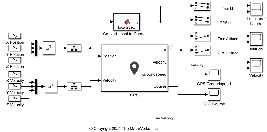
This model generates the X, Y, Z values, for both position and velocity, as individual sine waves and combines them using Mux blocks. Because the GPS block requires discrete signals, the combined position and velocity pass through Rate Transition blocks to the inputs to the Position and Velocity ports of the GPS block. The GPS block has default parameter settings except for the Vertical position accuracy, which is set to 1.5 due to the scale of the position and velocity.
Compare the outputs of the GPS block against the true signal values using Scope blocks. To do this for position, the local position coordinates will need to be converted to LLA coordinates. Use ned2lla function in the MATLAB Function block to convert the NED coordinates to LLA coordinates.
A MATLAB Function block uses the ned2lla function to convert the local position coordinates of the true signal values to geodetic coordinates. The model then plots the outputs of the GPS block against the true signal values.
Run Model
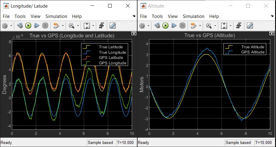
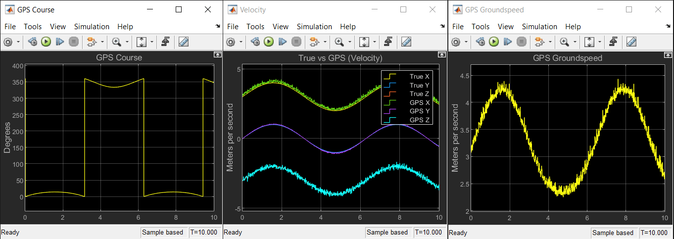
Run the model. The output scopes show the effect of the noise from the GPS sensor on the original and velocity outputs.