Create Motor Phase Current Sensing and Signal Conditioning Subsystem
In the physical hardware, the motor current read by the current sensors is filtered and scaled to an ADC measurable range. The ADC peripheral in the processor reads the current signals and outputs the ADC counts for the current control algorithm. This figure shows an example of how you can model the motor phase current sensing and signal conditioning algorithms.
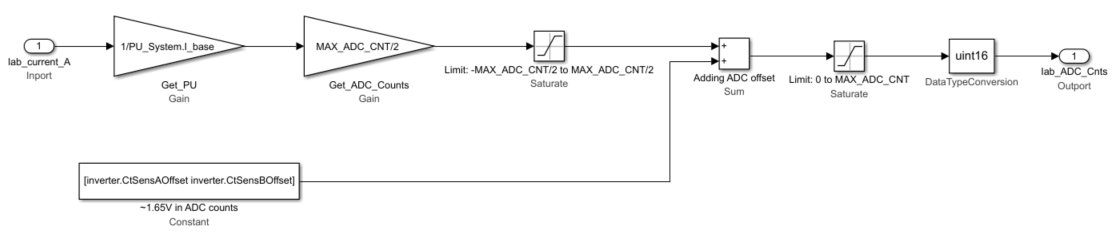
The maximum measurable peak current is considered as the base current. The ADC counts can be calculated from the base current and full-scale ADC values, along with the ADC offset, by using this equation:
For the default inverter and signal conditioning circuit parameters for commercially
available inverters, see the mcb.getInverterParameters.m file. To add
a new inverter configuration, create an inverter type in this file and use this in the
model initialization script for parameter initialization. If you are using low-pass
filters for measuring the current, add an average model to filter the current.