Pulsating High Freq Observer
Estimate initial rotor electrical position of interior PMSM using pulsating high frequency (PHF) injection
Since R2022b
Libraries:
Motor Control Blockset /
Sensorless Estimators
Description
The Pulsating High Frequency Observer block estimates the initial position (in electrical radians) of a stationary interior PMSM by using pulsating high-frequency (PHF) injection and dual-pulse (DP) techniques. In addition, the block also detects the real-time position when the rotor runs using (low-speed) closed-loop control.
For more information about the block algorithm, see Algorithm.
Examples

Estimate Initial Rotor Position Using Pulsating High-Frequency and Dual-Pulse Methods
Estimates the initial position (in electrical radians) of a stationary interior PMSM by using pulsating high-frequency (PHF) injection and dual pulse (DP) techniques.
Ports
Input
Output
Parameters
Algorithms
The block determines the best possible initial estimation for the rotor position using open-loop pulsating high-frequency (PHF) injection, which it uses to run closed-loop PHF.
The block executes closed-loop PHF by injecting a high-frequency signal into the estimated
rotor position to determine the actual rotor position without spinning the motor. This
technique works when the motor saliency ratio
(Lq/Ld)
is greater than 1. Due to a limitation in the PHF method, the estimated position can show
ambiguity equal to the value of π (pi). The dual-pulse (DP) method uses
polarity detection to resolve the ambiguity of π and applies a compensation
of π if there is an error. The estimated rotor position ranges from 0 to 2π
electrical radians.
The block can run in these two stages:
Stage 1 – Initial position estimation (IPE), which includes three parts.
Stage 2 – Closed-loop pulsating high-frequency (PHF) injection.
After Stage 1 completes, you can continue to run the block in Stage 2 where it computes the rotor position while the motor runs using closed loop control (for example, field-oriented control or FOC). Using the Stage 2 algorithm (closed-loop PHF injection), the block can continue to inject pulsating high frequency (as described in Part B) and use the numerical analysis of the resulting stator current response to compute and track the rotor position during closed-loop operation.
Stage 1 focuses on determining the initial position of the rotor when it is stationary. This stage includes the following three parts.
The block uses the PHF injection technique. PHF injection needs initial estimation to start the algorithm.
If you use only one initial estimation, θi_est, (for PHF) for all possible actual rotor positions, the block algorithm might not work accurately for certain actual rotor positions when the motor has low saliency. These ambiguous positions are:
When θactual lies in the range
When θactual lies in the range
When θactual lies in the range
To make PHF work for motors with low saliency, the block picks different initial estimation for different actual rotor positions.
The block picks the best possible initial estimation from these three alternatives:
θi_est =
0θi_est =
2π/3θi_est =
-2π/3
Therefore, the block sequentially injects three high-frequency voltage signals (that have the same peak amplitude Vphf and the same frequency fh) across the preceding 3 θi_est values and measures the resulting iq currents.
Note
In Part A, each high frequency voltage signal injection happens for a fixed time duration (Open loop duration (s) parameter). In addition, two consecutive injections have a fixed delay between them (Idle time (s) parameter).
The following equations describe the injected voltages in the estimated d-q reference frame:
The following equations describe the injected voltages in the estimated α-β reference frame:
The following equations describe the injected voltages in the actual d-q reference frame:
We can derive the following equation for the resulting iq current using the IPMSM motor dynamic equations:
Therefore,
where:
θi_est is the initial estimation of rotor position (which can be either
0,2π/3, or-2π/3) (in degrees, per-unit, or radians).θactual is the actual rotor position (in degrees, per-unit, or radians)
θerr = θactual – θi_est (in degrees, per-unit, or radians).
Ld and Lq are the d- and q-axis inductances of the IPMSM.
Vd_est and Vq_est are the voltages injected across the d- and q-axes of the estimated d-q reference frame.
Vd and Vq are the voltages injected across the d- and q-axes of the actual d-q reference frame.
Vα and Vβ are the voltages injected across the α- and β-axes of the stationary α-β reference frame.
with:
iq1 = iq_peak for θi_est = 0
iq2 = iq_peak for θi_est =
2π/3iq3 = iq_peak for θi_est =
-2π/3
For θi_est = 0, when you vary θactual from 0 to 2π, is the maximum value between the iq1, iq2, and iq3 current peak values when the rotor lies in the following four highlighted regions.
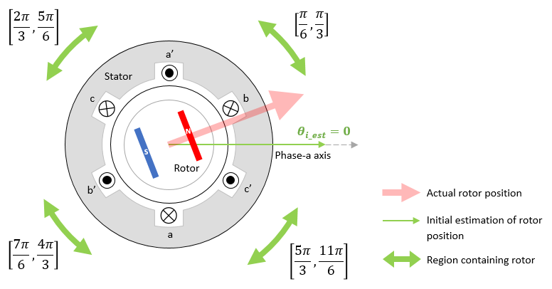
If θi_est = 0 is used for all
θactual = 0 to
2π, the algorithm fails for following ambiguous regions (when motor
saliency is low):
θactual lies in the range
θactual lies in the range
θactual lies in the range
Because these ambiguous regions are not present in the preceding four regions, you can eliminate the regions where the algorithm might fail.
For θi_est = (2π/3), when
you vary θactual from 0 to
2π, is the maximum value between the
iq1,
iq2, and
iq3 current peak values when the rotor lies in
the following four highlighted regions.

If θi_est = (2π/3) is used
for all θactual = 0 to
2π, the algorithm fails for following ambiguous regions (when motor
saliency is low):
θactual lies in the range
θactual lies in the range
θactual lies in the range
Because these ambiguous regions are not present in the preceding four regions, you can eliminate the regions where the algorithm might fail.
For θi_est = -(2π/3), when
you vary θactual from 0 to
2π, is the maximum value between
iq1,
iq2, and
iq3 current peak values when the rotor lies in
the following four highlighted regions.

If θi_est = -(2π/3) is used
for all θactual = 0 to
2π, the algorithm fails for following ambiguous regions (when motor
saliency is low):
θactual lies in the range
θactual lies in the range
θactual lies in the range
Because these ambiguous regions are not present in the preceding four regions, you can eliminate the regions where the algorithm might fail.
Therefore, using this approach you have three sets of regions corresponding to three different initial estimates. These three sets of regions cover all the motor sectors where the rotor can lie:
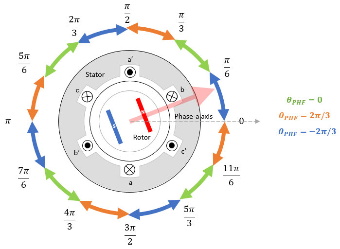
In part A, the block picks the θi_est corresponding to the maximum iq peak current value between iq1, iq2, and iq3 for Part B.
After determining the best possible initial estimate θi_est, the block injects a sinusoidal high-frequency voltage (with peak amplitude Vphf and frequency fh) along the finalized (θest | t = 0) = θi_est and reads the q-axis current response of the motor as described in Part A. However, in addition, it applies signal processing routines on the q-axis current response to make corrections to θest using a PI controller in a closed-loop configuration as shown below:

The following steps describe the signal processing routines used by the block:
Multiply the measured iq with cosine signal (with unit amplitude and frequency fh) to obtain the following signal:
Apply low-pass filter (LPF) to extract the bias term in the preceding result.
Negate the output of step 2.
From the output of the preceding 3 steps, we can derive the following error signal:
Because we can approximate sin(θ) to θ (when θ is close to zero), we can derive the following approximated error signal after considering that θerr is close to zero:
Therefore, using the preceding result, we can simplify model 1 as shown below:
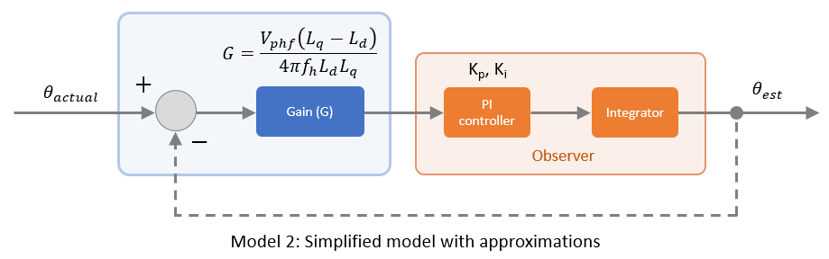
The following term represents the transfer function (simplified) of the entire model:
where, kp and ki proportional and integral gains of the PI controller.
Therefore, when the block executes, the estimated position is initially θi_est, but it rises steadily (dynamically according to G, kp, and ki gains) to saturate at a certain angle (with respect to a-axis) such that Error_signal is close to zero.
Note
In Part B, the high frequency voltage signal injection happens for a given time duration (Closed loop duration (s) parameter). Select this time duration such that the dynamics of θest reaches saturation.
The approximation used earlier introduces a limitation in the PHF method due to which the algorithm might compute the rotor position with an ambiguity of π. If the rotor lies in the range electrical radians (region 1), the estimated position is accurate (π compensation is not required).

If the rotor lies in the range electrical radians (region 2), the estimated position shows an ambiguity of π (π compensation is required).

Therefore, the block uses the dual-pulse method to determine if the estimated position
needs π compensation.
The block injects two very short duration voltage pulses (with the same width and magnitude) in the following positions:
Pulse 1 at the rotor position estimated in Part B
Pulse 2 at the rotor position estimated in Part B +
π
Because pulse width is very short, the motor does not run, and the rotor remains stationary after pulse injection.
The interaction between the resulting stator magnetic flux and the rotor permanent magnets results in two current impulses along the d-axis of the rotor that rise and fall quickly.
Because the stator core is saturated, it shows nonlinear behaviour. A small Ld results in higher current Id, and a high Ld results in smaller current Id. Therefore, the Id current impulses generated by Pulse 1 and Pulse 2 show different peak values.
Note
The pulse duration of the injected voltage pulses is large enough to obtain a measurable difference between the peak current values. At the same time, the duration is not too high, because, when the pulse duration exceeds a certain limit, the rotor may start spinning.

The block computes the difference between the peak values of the two current impulses ΔId to determine if the position estimated in Part A needs π compensation.
ΔId = |Id1| - |Id2|
PHF injection benefits use cases that require the rotor to remain stationary or that require position estimation without starting the motor. The PHF injection technique also benefits use cases where you need to avoid open loop runs to estimate position (before transitioning to closed-loop speed control) or where you require the motor to start directly in the closed-loop mode. The block algorithm in stage 1 algorithm addresses these use cases by estimating the position while keeping the rotor stationary and avoiding an open-loop run.
References
[1] W. Zine, L. Idkhajine, E. Monmasson, Z. Makni, P. Chauvenet, B. Condamin, and A. Bruyere, "Optimisation of HF signal injection parameters for EV applications based on sensorless IPMSM drives", IET Electric Power Applications, Volume 12, Issue 3, March 2018, p. 347 - 356 (doi:10.1049/iet-epa.2017.0228).
[2] Gaolin Wang, Guoqiang Zhang, and Dianguo Xu, "Position Sensorless Control Techniques for Permanent Magnet Synchronous Machine Drives", Springer, Singapore, 2020 p. 41 - 43 (doi: https://doi.org/10.1007/978-981-15-0050-3).
Extended Capabilities
Version History
Introduced in R2022b