Sensorless Field-Oriented Control of PMSM
This example implements the field-oriented control (FOC) technique to control the speed of a three-phase permanent magnet synchronous motor (PMSM). For details about FOC, see Field-Oriented Control.
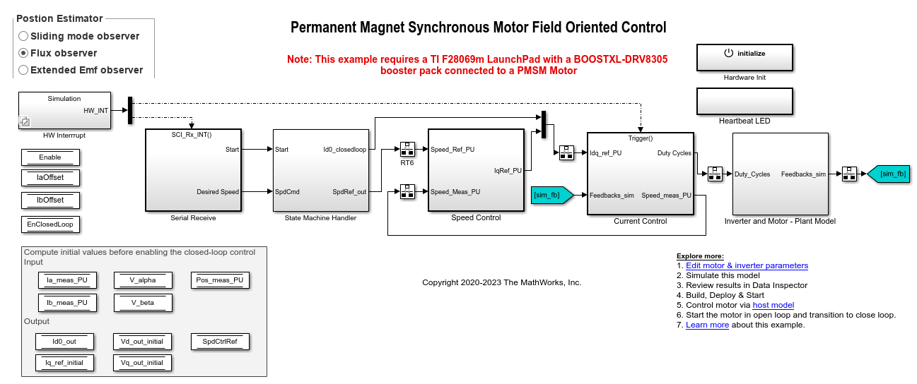
This example uses the sensorless position estimation technique. You can select either the sliding mode observer or flux observer or extended EMF observer to estimate the position feedback for the FOC algorithm used in the example.
The Sliding Mode Observer (SMO) block generates a sliding motion on the error between the measured and estimated position. The block produces an estimated value that is closely proportional to the measured position. The block uses stator voltages  and currents
  as inputs and estimates the electromotive force (emf) of the motor model. It uses the emf to further estimate the rotor position and rotor speed.
The Flux Observer block uses identical inputs  to estimate the stator flux, generated torque, and the rotor position.
The Extended EMF Observer block computes the electrical position,  (or
(or  and
and  ) in addition to the mechanical speed of PMSM from the measured voltage and current in the stationary alpha-beta reference frame.
To ensure that the detected rotor position is accurate, add the inverter board resistance value to the stator phase resistance parameter of the motor block and the stator resistance parameter of the Sliding Mode Observer, Flux Observer, and Extended EMF Observer blocks.
If you use flux observer, the example can run both PMSM and brushless DC (BLDC) motors.
The sensorless observers and algorithms have known limitations regarding motor operations beyond the base speed. We recommend that you use the sensorless examples for operations upto base speed only.
Transition from Open-Loop to Closed-Loop Control
Running a motor using closed-loop speed control requires accurate estimation of real-time motor position. The example uses sensorless observers for position estimation. However, sensorless position observers like flux observer, sliding mode observer, and extended EMF observer need measurable motor current and voltage values to successfully estimate the rotor position. To generate the currents and voltages needed for sensorless position estimation, the motor should run using open-loop control. After the sensorless observer successfully estimates the rotor position, transition from open-loop to closed-loop control can occur.
However, successful completion of this transition can be challenging as it may result in difficulties in determining accurate PI control gains as well as other parameters due to motor dynamics. This example shows a simplified method to achieve this transition smoothly. The method includes these three stages:
Start and run motor using open-loop control.
Switch to closed-loop using maximum open-loop speed limit value.
Follow given reference speed using closed-loop control.
Stage - 1: Start and Run Motor Using Open-Loop Control
The example starts and runs the motor using open-loop control. Running a motor using open-loop control depends on the d-axis voltage (Vd) and maximum open-loop speed limit parameters. The default value of Vd used by the example may not be sufficient for motors with high inertia or high friction. Therefore, it is recommended that you increase the minimum limit of Vd. Because increasing the minimum limit of Vd increases the motor current and motor temperature, we recommend that you increase the minimum limit of Vd in small steps. Use the variable MIN_OL_VD_LIMIT (available in the model initialization script mcb_pmsm_foc_sensorless_f28069MLaunchPad_datascript or mcb_pmsm_foc_sensorless_f28379d_datascript associated with the example) to change the minimum limit of Vd.
After the sensorless observer starts tracking rotor position, the example moves to Stage - 2.
Stage - 2: Switch to Closed-Loop Using Maximum Open-Loop Speed Limit Value
During this stage you can verify if that the sensorless observers use the minimum current value (Id) corresponding to Vd to estimate the rotor position successfully.
The example begins this stage by running the motor using maximum open-loop speed limit (defined by either
MAX_OL_POS_SPDorMAX_OL_NEG_SPDvariable available in the model initialization script).
Note: You can adjust MAX_OL_POS_SPD and MAX_OL_NEG_SPD values to ensure that enough current (Id) is generated for the example to successfully estimate the rotor position.
Verify if the sensorless observers compute the real-time rotor position values successfully.
Afterwards, the example initializes the d-axis current (Id), q-axis current (Iq), and speed PI controllers to enable the closed-loop field-oriented control (FOC). Ensure that you set the initial variable values (Iq, Vd, and Vq) for PI controllers in the model initialization script.
This example uses the sub-system State Machine Handler/Compute Control-loop Initial Values to compute the default initial values of Iq, Vd, and Vq. It also utilizes the computed initial values available within the PI control loop.
The example ensures that the initial value of the controller remains unchanged when Id, Iq, and speed PI controllers are enabled for the first time. The integrator available within these three PI control loops uses the initial value, 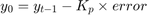 (where,
  is the previous value and
  is the controller gain).
The example then uses Stateflow® to gradually ramp down the current Id from the presently measured value to zero.
Note: After transitioning to closed-loop, you may directly use the rotor position (estimated by the sensorless observer), reference Id current (set to zero), and reference Iq current (obtained from the speed control loop). However, using this approach causes current transients, which distort the output of the sensorless position estimator. To enable a smooth current transition, the example ramps down current Id to zero. You can use the variable RAMP_STEP_SIZE available in the model initialization script to set the rate for Id current ramp down, which is performed by the Stateflow.
Stage - 3: Follow Given Reference Speed Using Closed-Loop Control
After the example ramps down Id to zero, the example enters this stage, where it uses FOC algorithm to run the motor by following a given closed-loop reference speed.
Note: To change the motor direction, the Stateflow changes the motor speed from the current closed-loop speed to the maximum open-loop speed limit to transition to open-loop mode. It then changes the motor direction during the open-loop operation after which, it transitions back to closed-loop control and follows the reference speed. You can utilize the additional time taken by the motor dynamics and make adjustments to accommodate delays in the Stateflow.
Models
The example includes these models:
mcb_pmsm_foc_sensorless_f28069MLaunchPad
mcb_pmsm_foc_sensorless_f28379d
You can use these models for both simulation and code generation.
For the model names that you can use for different hardware configurations, see the Required Hardware topic in the Generate Code and Deploy Model to Target Hardware section.
Required MathWorks Products
To simulate model:
1. For the model: mcb_pmsm_foc_sensorless_f28069MLaunchPad
Motor Control Blockset™
Fixed-Point Designer™
Stateflow (needed only if you modify the example model)
2. For the model: mcb_pmsm_foc_sensorless_f28379d
Motor Control Blockset
Stateflow (needed only if you modify the example model)
To generate code and deploy model:
1. For the model: mcb_pmsm_foc_sensorless_f28069MLaunchPad
Motor Control Blockset
Embedded Coder®
C2000™ Microcontroller Blockset
Fixed-Point Designer
Stateflow (needed only if you modify the example model)
2. For the model: mcb_pmsm_foc_sensorless_f28379d
Motor Control Blockset
Embedded Coder
C2000 Microcontroller Blockset
Fixed-Point Designer (only needed for optimized code generation)
Stateflow (needed only if you modify the example model)
Prerequisites
1. Obtain the motor parameters. We provide default motor parameters with the Simulink® model that you can replace with the values from either the motor datasheet or other sources.
However, if you have the motor control hardware, you can estimate the parameters for the motor that you want to use, by using the Motor Control Blockset parameter estimation tool. For instructions , see Estimate Motor Parameters Using Motor Control Blockset Parameter Estimation Tool.
The parameter estimation tool updates the motorParam variable (in the MATLAB® workspace) with the estimated motor parameters.
2. If you obtain the motor parameters from the datasheet or other sources, update the motor parameters and inverter parameters in the model initialization script associated with the Simulink models. For instructions, see Estimate Control Gains and Tune Control Parameters.
If you use the parameter estimation tool, you can update the inverter parameters, but do not update the motor parameters in the model initialization script. The script automatically extracts motor parameters from the updated motorParam workspace variable.
Sliding Mode Observer parameters require tuning if you are using Sliding Mode Observer with the motor parameters estimated using the parameter estimation tool.
Simulate Model
This example supports simulation. Follow these steps to simulate the model.
1. Open a target model included with this example.
2. Use the Position Estimator button to select one of the following sensorless position estimation techniques:
3. To simulate the model, click Run on the Simulation tab.
4. To view and analyze the simulation results, click Data Inspector on the Simulation tab.
Generate Code and Deploy Model to Target Hardware
This section instructs you to generate code and run the FOC algorithm on the target hardware.
This example uses a host and a target model. The host model is a user interface to the controller hardware board. You can run the host model on the host computer. The prerequisite to use the host model is to deploy the target model to the controller hardware board. The host model uses serial communication to command the target Simulink model and run the motor in a closed-loop control.
Required Hardware
This example supports these hardware configurations. You can also use the target model name to open the model for the corresponding hardware configuration, from the MATLAB® command prompt.
LAUNCHXL-F28069M controller + BOOSTXL-DRV8305 inverter:
mcb_pmsm_foc_sensorless_f28069MLaunchPad
LAUNCHXL-F28379D controller + (BOOSTXL-DRV8305 or BOOSTXL-3PHGANINV) inverter:
mcb_pmsm_foc_sensorless_f28379d
For connections related to the preceding hardware configurations, see LAUNCHXL-F28069M and LAUNCHXL-F28379D Configurations.
Generate Code and Run Model on Target Hardware
1. Simulate the target model and observe the simulation results.
2. Complete the hardware connections.
3. The model automatically computes the Analog-to-Digital Converter (ADC) or current offset values. To disable this functionality (enabled by default), update the value 0 to the variable inverter.ADCOffsetCalibEnable in the model initialization script.
Alternatively, you can compute the ADC offset values and update it manually in the model initialization scripts. For instructions, see Run 3-Phase AC Motors in Open-Loop Control and Calibrate ADC Offset.
4. Open the target model for the hardware configuration that you want to use. If you want to change the default hardware configuration settings for the model, see Model Configuration Parameters.
5. Load a sample program to CPU2 of LAUNCHXL-F28379D, for example, program that operates the CPU2 blue LED using GPIO31 (c28379D_cpu2_blink.slx), to ensure that CPU2 is not mistakenly configured to use the board peripherals intended for CPU1. For more information about the sample program or model, see the Task 2 - Create, Configure and Run the Model for TI Delfino F28379D LaunchPad (Dual Core) section in Getting Started with Texas Instruments C2000 Microcontroller Blockset (C2000 Microcontroller Blockset).
6. Use the Position Estimator button to select a sensorless position estimation technique.
7. Click Build, Deploy & Start on the Hardware tab to deploy the target model to the hardware.
8. In the target model, click the mcb_host_model_f28069m.slx host model hyperlink to open the associated host model.

For details about the serial communication between the host and target models, see Host-Target Communication.
9. In the model initialization script associated with the target model, specify the communication port using the variable target.comport. The example uses this variable to update the Port parameter of the Host Serial Setup, Host Serial Receive, and Host Serial Transmit blocks available in the host model.
10. Update the Reference Speed value in the host model.
NOTE:
Before you run the motor at the required Reference Speed (by using either Sliding Mode Observer, Flux Observer, or Extended EMF Observer), start running the motor at 0.1 x
pmsm.N_basespeed by using open-loop control. Then transition to closed-loop control by increasing the speed to 0.25 xpmsm.N_base(where,pmsm.N_baseis the MATLAB workspace variable for base speed of the motor).
High acceleration and deceleration may affect the sensorless position computation.
11. Click Run on the Simulation tab to run the host model.
12. Change the position of the Start / Stop Motor switch to On, to start running the motor in the open-loop condition (by default, the motor spins at 10% of base speed).
NOTE: Do not run the motor (using this example) in the open-loop condition for a long time duration. The motor may draw high currents and produce excessive heat.
We designed the open-loop control to run the motor with a Reference Speed that is less than or equal to 10% of base speed.
When you run this example on the hardware at a low Reference Speed, due to a known issue, the PMSM may not follow the low Reference Speed.
13. Increase the motor Reference Speed beyond 10% of base speed to switch from open-loop to closed-loop control.
NOTE: To change the motor's direction of rotation, reduce the motor Reference Speed to a value less than 10% of the base speed. This brings the motor back to open-loop condition. Change the direction of rotation but keep the Reference Speed magnitude as constant. Then transition to the closed-loop condition.
14. Observe the debug signals from the RX subsystem, in the Time Scope of host model.
NOTE:
A high reference speed and a high reference torque can affect the Sliding Mode Observer block performance.
If you are using a F28379D based controller, you can also select the debug signals that you want to monitor.
Other Things to Try
You can use SoC Blockset™ to implement a sensorless closed-loop motor control application that addresses challenges related to ADC-PWM synchronization, controller response, and studying different PWM settings. For details, see Integrate MCU Scheduling and Peripherals in Motor Control Application.
You can also use SoC Blockset™ to develop a sensorless real-time motor control application that utilizes multiple processor cores to obtain design modularity, improved controller performance, and other design goals. For details, see Partition Motor Control for Multiprocessor MCUs.
See Also
Sliding Mode Observer | Flux Observer | Pulsating High Freq Observer | Extended EMF Observer