Estimate PMSM Parameters Using Parameter Estimation Blocks on Real-Time Systems
This example uses the parameter estimation blocks provided by Motor Control Blockset™ to estimate these parameters of a permanent magnet synchronous motor (PMSM):
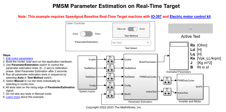
Phase resistance, Rs (Ohm)
D-axis inductance, Ld (Henry)
Q-axis inductance, Lq (Henry)
Back-EMF constant, Ke (Vpk_LL/krpm, where Vpk_LL is the peak voltage line-to-line measurement)
Motor inertia, J (Kg.m^2)
Friction constant, B (N.m.s)
Motor parameter estimation is vital for implementing motor control algorithms accurately. Accurate motor parameters enable the algorithm to compute the control parameters with precision. Therefore, an accurate representation of motor parameters results in efficient speed tracking when you run PMSMs using control techniques such as field-oriented control (FOC). Motor parameter estimation also enables you to verify the parameter values provided by the motor datasheet. In addition, it enables you to accurately replicate the plant model in Simulink® using which you can simulate real-world scenarios and tests that are difficult to execute using a physical hardware setup.
An accurate simulation helps you reconfigure and run these tests multiple times, which can be difficult when you use physical hardware. Therefore, these exhaustive tests enable you to predict, find, and fix problems with ease including failures that are hard-to-reproduce.
The example shows you how to use these blocks to design and implement a PMSM parameter estimation algorithm on a Speedgoat® hardware:
PMSM Parameter Estimation Configurator
PMSM Rs Estimator
Ld Estimator
Lq Estimator
PMSM Mechanical Parameter Estimation
Alternatively, using this example as a reference, you can utilize these blocks to implement a similar algorithm on a different hardware or configuration.
The target model included in the example uses the parameter estimation blocks in the mcb_pmsm_param_est_speedgoat/Parameter Estimation/Parameter Estimation subsystem:

These subsystems use the parameter estimation blocks to estimate Rs, Ld, Lq, and the mechanical parameters:
Rs Estimation— Uses the Rs Estimator block to estimate the motor resistance.
Ld Estimation— Uses the Ld Estimator block to estimate d-axis inductance.
Lq Estimation— Uses the Lq Estimator block to estimate q-axis inductance.
Mechanical Parameter Estimation— Uses the PMSM Mechanical Parameter Estimation block to estimate the back-EMF constant, motor inertia, and the friction constant.
The target model included in the example runs on the hardware in external mode. After running the parameter estimation tests, the target model displays the estimated parameters.
Model
The example includes the mcb_pmsm_param_est_speedgoat model.
You can use the model for both simulation and code generation.
For details about the supported hardware configuration, see Required Hardware in the Generate Code and Deploy Model to Target Hardware section.
Required MathWorks Products
Motor Control Blockset
Simulink Real-Time™
Stateflow® (needed only if you modify the example model)
Additional Product
Speedgoat I/O Blockset (from Speedgoat)
Prerequisite
Check and update the mandatory motor, inverter, and other system parameters listed in the model initialization script mcb_pmsm_param_est_speedgoat_data.m.
In addition, you can update the optional motor parameters for simulation.
You can use the inverter and motor hardware datasheet to determine these values.
Simulate Model
This example supports simulation. Follow these steps to simulate the model.
1. Open the target model included in this example.
2. If required, change the configuration elements for parameter estimation, by updating the mask parameters of the PMSM Parameter Estimation Configurator block available in the mcb_pmsm_param_est_speedgoat/System Inputs subsystem. For more details, see PMSM Parameter Estimation Configurator.
3. In the User Controls section, ensure that the Parameter Estimation switch is set to Stop.
4. Click Run on the Simulation tab to simulate the model. The model performs current and position sensor calibration for the first two seconds. Proceed to the next steps after two seconds.
5. Set the Test Method switch to either Manual or Auto mode.
- Manual — This mode enables you to manually execute the tests one by one in the prescribed sequence.
- Auto — This mode enables you to automatically run all the tests in the prescribed sequence.
If you are using Manual mode:
a. Set the Test Method switch to Manual.
b. Use the Test Select button to select the first test Rs.
c. Turn the Parameter Estimation switch to Start. The model runs the Rs estimation test, after which it displays the computed value in the Estimated Parameters field.
d. Turn the Parameter Estimation switch to Stop.
e. Similarly, use the Test Select button to select the next test and repeat steps c to e.
Note: Ensure that you run all tests in the prescribed sequence of Rs > Ld > Lq > (Ke, J, B). Do not skip any test.
During simulation, the target model does not support computation of J.
The target model uses the Active Test field to display the test that is currently running.
If you are using Auto mode:
a. Set the Test Method switch to Auto.
b. Turn the Parameter Estimation switch to Start. The model starts running all tests in the prescribed sequence of Rs > Ld > Lq > (Ke, J, B) after which it displays the computed parameter values in the Estimated Parameters field.
c. Turn the Parameter Estimation switch to Stop.
Note: In the Auto mode, the Test Select button selection has no effect.
During simulation, the target model does not support computation of J.
The target model uses the Active Test field to display the test that is currently running.
Generate Code and Deploy Model to Target Hardware
This section shows you how to generate code and run the parameter estimation algorithm on the target hardware to estimate parameters of the connected motor.
Required Hardware
This example supports Speedgoat Electric Motor Control Kit (Baseline real-time target machine with IO397 I/O module and Electric Motor Control Kit) that includes these components:
Three-phase inverter rated for 48V and 20A from Speedgoat
100W three-phase brushless DC motor from Maxon Motor
Quadrature encoder with 4096 counts per revolution
150W 24V DC power supply
Note: Contact Speedgoat for the bit stream file related to your hardware.
For details about the Speedgoat hardware setup, navigate to Speedgoat Software Configuration Guide from this page.
Generate Code and Run Model on Target Hardware
1. Complete the hardware connections for the Speedgoat Electric Motor Control Kit.
2. Open the target model.
3. If required, change the configuration elements for parameter estimation, by updating the mask parameters of the PMSM Parameter Estimation Configurator block available in the mcb_pmsm_param_est_speedgoat/System Inputs subsystem. For more details, see PMSM Parameter Estimation Configurator.
4. Check and update the rotor direction using the A leads B parameter of the Condition Encoder block available in the subsystem mcb_pmsm_param_est_speedgoat/Parameter Estimation/Input HW Drivers/Codegen.
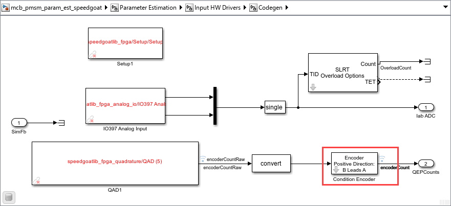
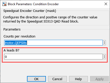
To determine the parameter value, you can either contact Speedgoat or follow the instructions in the Run motor in open-loop control section of the Tune PI Controllers Using Field Oriented Control Autotuner Block on Real-Time Systems example.
5. In the Real-Time tab on the Simulink toolstrip, select the Speedgoat kit under Target Platform.
6. In the Real-Time tab on the Simulink toolstrip, click Run on Target to build and load the model to the hardware and start running the model in external mode.
The model performs current and position sensor calibration for the first two seconds. Proceed to the next steps after two seconds.
7. In the User Controls section, ensure that the Test Enable switch is set to Off.
8. Use the Test Method switch to select either Manual or Auto mode.
- Manual — This mode enables you to manually execute the tests one by one in the prescribed sequence.
- Auto — This mode enables you to automatically run all the tests in the prescribed sequence.
If you are using Manual mode:
a. Set the Test Method switch to Manual.
b. Use the Test Select button to select the first test Rs.
c. Turn the Parameter Estimation switch to Start. The model runs the Rs estimation test, after which it displays the computed value in the Estimated Parameters field.
d. Turn the Parameter Estimation switch to Stop.
e. Similarly, use the Test Select button to select the next test and repeat steps c to e.
Note: Ensure that you run all tests in the prescribed sequence of Rs > Ld > Lq > (Ke, J, B). Do not skip any test.
The target model uses the Active Test field to display the test that is currently running.
If you are using Auto mode:
a. Set the Test Method switch to Auto.
b. Turn the Parameter Estimation switch to Start. The model starts running all tests in the prescribed sequence of Rs > Ld > Lq > (Ke, J, B) after which it displays the computed parameter values in the Estimated Parameters field.
c. Turn the Parameter Estimation switch to Stop.
Note: In the Auto mode, the Test Select button selection has no effect.
The target model uses the Active Test field to display the test that is currently running.
See Also
Apps
Blocks
- PMSM Rs Estimator | Ld Estimator | Lq Estimator | PMSM Mechanical Parameter Estimator | PMSM Parameter Estimation Configurator | ACIM Parameter Estimation Configurator | Id0 Estimator | ACIM Rs Estimator | RrL Estimator | ACIM Mechanical Parameter Estimator
Topics
- Estimate PMSM Parameters Using Custom Hardware
- Estimate Induction Motor Parameters Using Parameter Estimation Blocks
- Estimate PMSM Parameters Using Parameter Estimation Blocks
- Estimate PMSM Parameters Using FPGA-Based Motor Control Development Kit
- Run-Time Parameter Estimation of PMSM Using Sensor Feedback
- Generate Motor Control Models for Selected Algorithm and Hardware