Main Content

lteEqualizeMMSE

MMSE equalization

Description

example

[out,csi] = lteEqualizeMMSE(rxgrid,channelest,noiseest) returns equalized data in multidimensional array, out. MMSE equalization is applied to the received data resource grid in the matrix, rxgrid, using the channel information in the channelest matrix. noiseest is an estimate of the received noise power spectral density.

Alternatively, the input channelest can be provided as a 3-D array of size NRE-by-NRxAnts-by-P, and the input rxgrid can be provided as a matrix of size NRE-by-NRxAnts. In this case, the first two dimensions have been reduced to one dimension by appropriate indexing through the frequency and time locations of the resource elements of interest, typically for a single physical channel. The outputs, out and csi, are of size (N×M)-by-P.

Examples

collapse all

Equalize the received signal for RMC R.4 after channel estimation. Use the MMSE equalizer.

Create cell-wide configuration structure and generate transmit signal. Configure propagation channel.

enb = lteRMCDL('R.4');
[txSignal,~,info] = lteRMCDLTool(enb,[1;0;0;1]);

chcfg.DelayProfile = 'EPA';
chcfg.NRxAnts = 1;
chcfg.DopplerFreq = 70;
chcfg.MIMOCorrelation = 'Low';
chcfg.SamplingRate = info.SamplingRate;
chcfg.Seed = 1;
chcfg.InitPhase = 'Random';
chcfg.InitTime = 0;

txSignal = [txSignal; zeros(15,1)];
N = length(txSignal);
noise = 1e-3*complex(randn(N,chcfg.NRxAnts),randn(N,chcfg.NRxAnts));
rxSignal = lteFadingChannel(chcfg,txSignal)+noise;

Perform synchronization and OFDM demodulation.

offset = lteDLFrameOffset(enb,rxSignal);
rxGrid = lteOFDMDemodulate(enb,rxSignal(1+offset:end,:));

Create channel estimation configuration structure and perform channel estimation.

cec.FreqWindow = 9;
cec.TimeWindow = 9;
cec.InterpType = 'Cubic';
cec.PilotAverage = 'UserDefined';
cec.InterpWinSize = 3;
cec.InterpWindow = 'Causal';
[hest,noiseEst] = lteDLChannelEstimate(enb, cec, rxGrid);

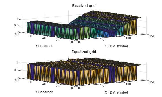
Equalize and plot received and equalized grids.

eqGrid = lteEqualizeMMSE(rxGrid, hest, noiseEst);
subplot(2,1,1)
surf(abs(rxGrid))
title('Received grid')
xlabel('OFDM symbol')
ylabel('Subcarrier')

subplot(2,1,2)
surf(abs(eqGrid))
title('Equalized grid')
xlabel('OFDM symbol')
ylabel('Subcarrier')

Figure contains 2 axes objects. Axes object 1 with title Received grid, xlabel OFDM symbol, ylabel Subcarrier contains an object of type surface. Axes object 2 with title Equalized grid, xlabel OFDM symbol, ylabel Subcarrier contains an object of type surface.

This example applies MMSE equalization on the received signal for reference measurement channel (RMC) R.5, after channel estimation.

Set the DL reference measurement channel to R.5

enb = lteRMCDL('R.5');

Set channel estimator configuration PilotAverage field to UserDefined. as follows: averaging window of 9 resource elements in both frequency and time domain, cubic interpolation with a casual window.

cec = struct('FreqWindow',9,'TimeWindow',9,'InterpType','cubic');
cec.PilotAverage = 'UserDefined';
cec.InterpWinSize = 1;
cec.InterpWindow = 'Causal';

Generate the txWaveform.

txWaveform = lteRMCDLTool(enb,[1;0;0;1]);
n = length(txWaveform);

Apply some random noise to the transmitted signal and save as the rxWaveform.

rxWaveform = repmat(txWaveform,1,2)+complex(randn(n,2),randn(n,2))*1e-3;

Next, demodulate the received data.

rxGrid = lteOFDMDemodulate(enb,rxWaveform);

Then, perform channel estimation.

[hest,n0] = lteDLChannelEstimate(enb,cec,rxGrid);

Finally, apply the MMSE equalization.

out = lteEqualizeMMSE(rxGrid,hest,n0);

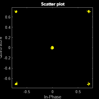
Show scatter plot of one component carrier.

scatterplot(out(:,1))

Figure Scatter Plot contains an axes object. The axes object with title Scatter plot, xlabel In-Phase, ylabel Quadrature contains a line object which displays its values using only markers. This object represents Channel 1.

Input Arguments

collapse all

Received data resource grid, specified as a 3-D numeric array or a 2-D numeric matrix. As a 3-D numeric array, it has size N-by-M-by-NRxAnts, where N is the number of subcarriers, M is the number of OFDM symbols, and NRxAnts is the number of receive antennas.

Alternatively, as a 2-D numeric matrix, it has size NRE-by-NRxAnts. In this case, the first two dimensions have been reduced to one dimension by appropriate indexing through the frequency and time locations of the resource elements of interest, typically for a single physical channel.

Data Types: double
Complex Number Support: Yes

Channel information, specified as a 4-D numeric array or a 3-D numeric array. As a 4-D numeric array, it has size N-by-M-by-NRxAnts-by-P. N is the number of subcarriers, M is the number of OFDM symbols, NRxAnts is the number of receive antennas, and P is the number of transmit antennas. Each element is a complex number representing the narrowband channel for each resource element and for each link between transmit and receive antennas. This matrix can be obtained using the channel estimation command lteDLChannelEstimate.

Alternatively, as a 3-D numeric array, it has size NRE-by-NRxAnts-by-P. In this case, the first two dimensions have been reduced to one dimension by appropriate indexing through the frequency and time locations of the resource elements of interest, typically for a single physical channel.

Data Types: double
Complex Number Support: Yes

Noise power estimate, specified as a numeric scalar. It is an estimate of the received noise power spectral density per RE on rxgrid.

Data Types: double

Output Arguments

collapse all

Equalized output data, returned as a 3-D numeric array or a 2-D numeric matrix. As a 3-D numeric array, it has size N-by-M-by-P, where N is the number of subcarriers, M is the number of OFDM symbols, and P is the number of transmit antennas.

Alternatively, if channelest is provided as a 3-D array, out is a 2-D numeric matrix of size (N×M)-by-P. In this case, the first two dimensions have been reduced to one dimension by appropriate indexing through the frequency and time locations of the resource elements of interest, typically for a single physical channel.

Data Types: double
Complex Number Support: Yes

Soft channel state information, returned as a 3-D numeric array of the same size as out. As a 3-D numeric array, it has size N-by-M-by-P, where N is the number of subcarriers, M is the number of OFDM symbols, and P is the number of transmit antennas. csi provides an estimate (via MMSE) of the received RE gain for each received RE.

Alternatively, if channelest is provided as a 3-D array, csi is a 2-D numeric matrix of size (N×M)-by-P. In this case, the first two dimensions have been reduced to one dimension by appropriate indexing through the frequency and time locations of the resource elements of interest, typically for a single physical channel.

Data Types: double

Version History

Introduced in R2014a