Servo Valve with Custom Fidelity
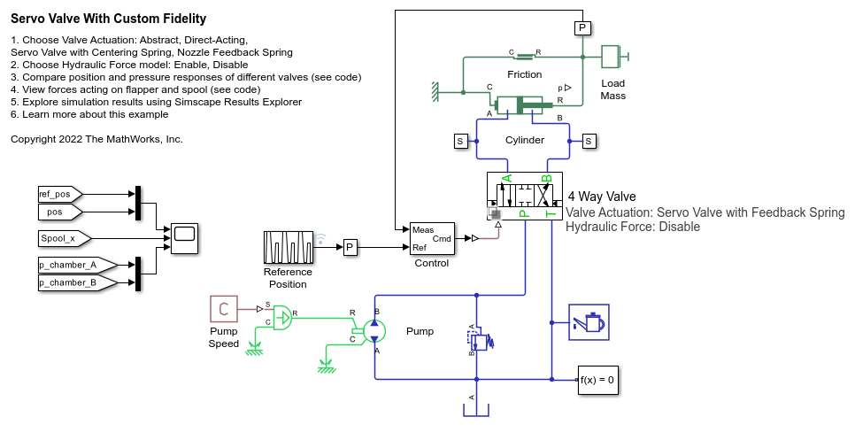
This example compares the mechanical performance of various spool actuation configurations and model fidelity levels for a hydraulic 4-way 3-position directional valve. The directional valve controls a simple double-acting cylinder in a closed-loop application. This example allows you to choose among four different spool actuation designs:
abstract actuator,
direct-acting electromagnetic actuator with a centering spring,
servo valve with a centering spring,
servo valve with a feedback spring.
For any of these valve types, you can enable or disable forces acting on the spool due to fluid flowing through the orifices.
Model

Valve with an Abstract Actuator
The simplest valve variant models the spool actuator abstractly as a first-order lag relation between the valve control command and the spool position.


Direct-Operated Valve
The second valve variant models an electromagnetic actuator that directly drives the directional valve spool. The directional valve contains a centering spring.

The subsystem for this valve variant contains an Ideal Force Source to abstractly represent the electromagnetic actuator and other translational mechanical elements to represent the spool and centering spring. The motion of this mechanical system drives the opening and closing of orifices that permit fluid flow in the Orifices subsystem.

Servo Valve with a Centering Spring
The third valve variant is a two-stage servo valve with a flapper-nozzle amplifier in the pilot stage and the 4-way 3-position spool valve in the power stage. This servo valve does not contain a feedback spring. Both the flapper and directional valve spool contain centering springs. The torque motor drives flapper motion, which varies the nozzle openings, and, in turn, varies the pressure acting on either side of the spool.

The subsystem for this valve variant contains an Ideal Force Source to represent the torque motor and other translational mechanical elements to represent the flapper and flapper centering spring. A hard stop constrains the flapper motion to remain within the allowable space in the valve cavity. The flapper displacement adjusts the nozzle openings represented by Orifice (IL) blocks. The nozzle openings affect the pressure of the fluid that feeds into the chambers on either end of the spool.

The subsystem for the power stage models the spool motion and spool centering spring using translational mechanical blocks. A double-Acting Actuator (IL) block couples the spool translational dynamics with the fluid pressure in the chambers on either end of the spool. The motion of this mechanical system drives the Orifices subsystem that models fluid flow through the spool orifices.

Servo Valve with a Flapper Nozzle Feedback Spring
The servo valve with a feedback spring configuration is a two-stage servo valve with a 4-way, 3-position spool valve in the power stage and a flapper-nozzle amplifier in the pilot stage. The flapper is connected to the armature of a torque motor. The servo valve in this configuration is equipped with the spring feedback between the flapper and the spool of the main valve.

The subsystem for this valve variant is similar to the subsystem for the servo valve with a centering spring, except that instead of a centering spring that is grounded on one side, there is a translational mechanical flapper spring between the flapper and the spool.

The subsystem for the power stage is similar to the subsystem for the servo valve with a centering spring, except this subsystem does not contain a spool centering spring.

Orifice AT Subsystem
The fluid flow through each of the spool valve orifices is modeled using Spool Orifice (IL) blocks. These blocks can optionally model the steady state flow force acting on the spool.

Simulation Results from Simscape Logging
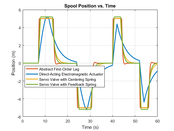
The plots below show the cylinder position, cylinder pressure, spool position, and electromagnetic actuator force versus time for the four different spool actuation designs. Among the non-abstract valve variants, the servo valve with the feedback spring responds the fastest to changes in the reference position command and its electromagnetic actuator requires the least amount of force. The direct-acting electromagnetic actuator needs to exert significantly more force than the servo valves to move the spool. The valve with the abstract first-order lag actuator has been tuned to match the motion response of the servo valve with the feedback spring.
Testing Valve Type: Abstract First-Order Lag. Hydraulic Forces: Disable
Testing Valve Type: Direct-Acting Electromagnetic Actuator. Hydraulic Forces: Disable
Testing Valve Type: Servo Valve with Centering Spring. Hydraulic Forces: Disable
Testing Valve Type: Servo Valve with Feedback Spring. Hydraulic Forces: Disable


The plot below shows the dominant forces exerted on the flapper and the spool.
