EV Battery Thermal Management System
This example shows an Electric Vehicle (EV) battery heating-cooling system. Maintaining the battery temperature within an optimal range is important for efficient charging and discharging. The model simulates either the FTP-75 drive cycle or a fast charge cycle at different environment temperatures. A thermal liquid coolant circuit conveys heat between the battery and the heating-cooling unit. For more information on designing EV battery cooling systems, see EV Battery Cooling System Design.
Model
open_system("EVBatteryThermalManagementSystem");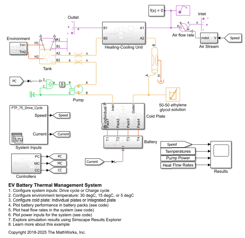
Battery and Cold Plate
The battery is composed of four battery packs connected in series. The battery packs interface with the cold plate to release or absorb heat. The data used for each cell comes from [1].
open_system('EVBatteryThermalManagementSystem/Battery')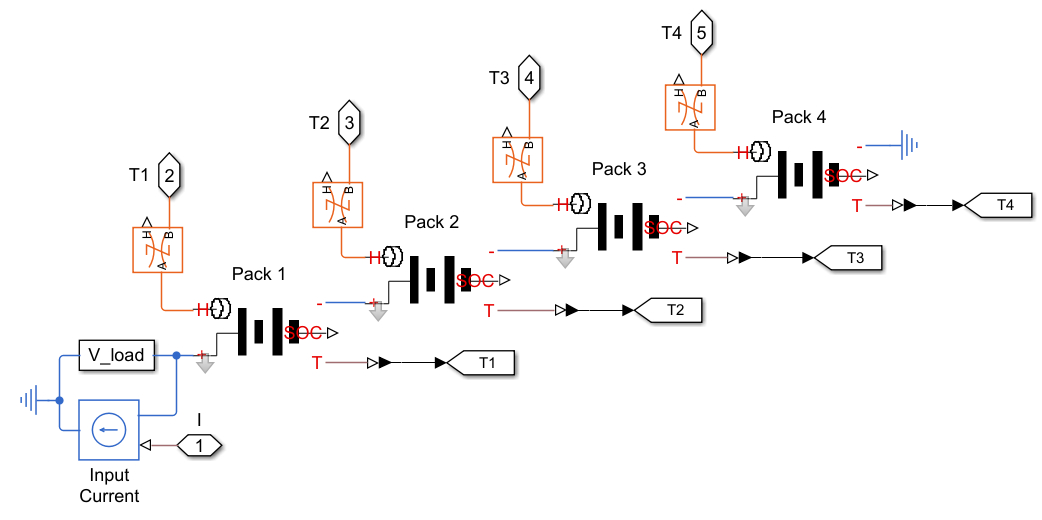
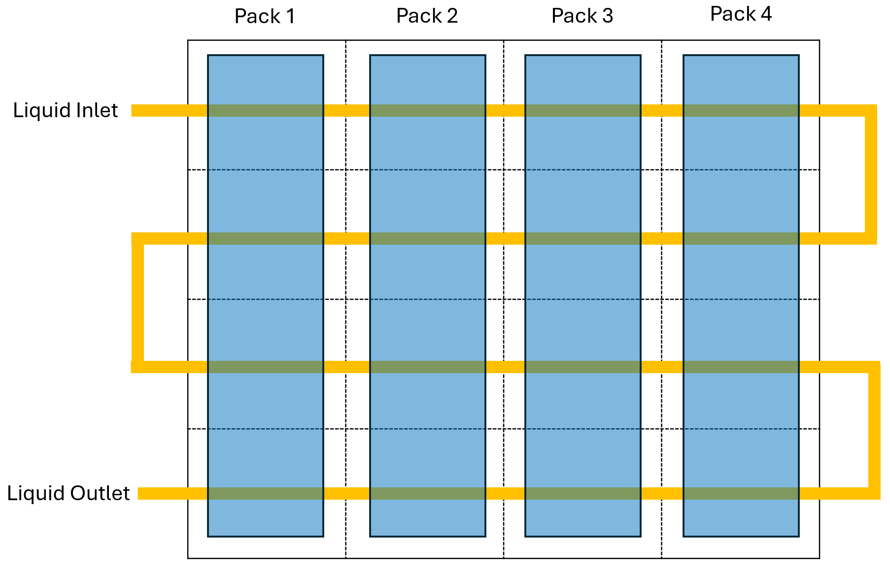
There are two possible variants for the cold plate: Individual plates and an integrated plate. The individual plates variant consists of four individual cooling plates that each interface with a battery pack. Each cooling plate has thermal liquid channels through which the corresponding battery pack dumps or absorbs heat. In this schematic, a blue rectangle represents a battery pack, and a white background rectangle is a cooling plate. Yellow lines denote liquid channels.
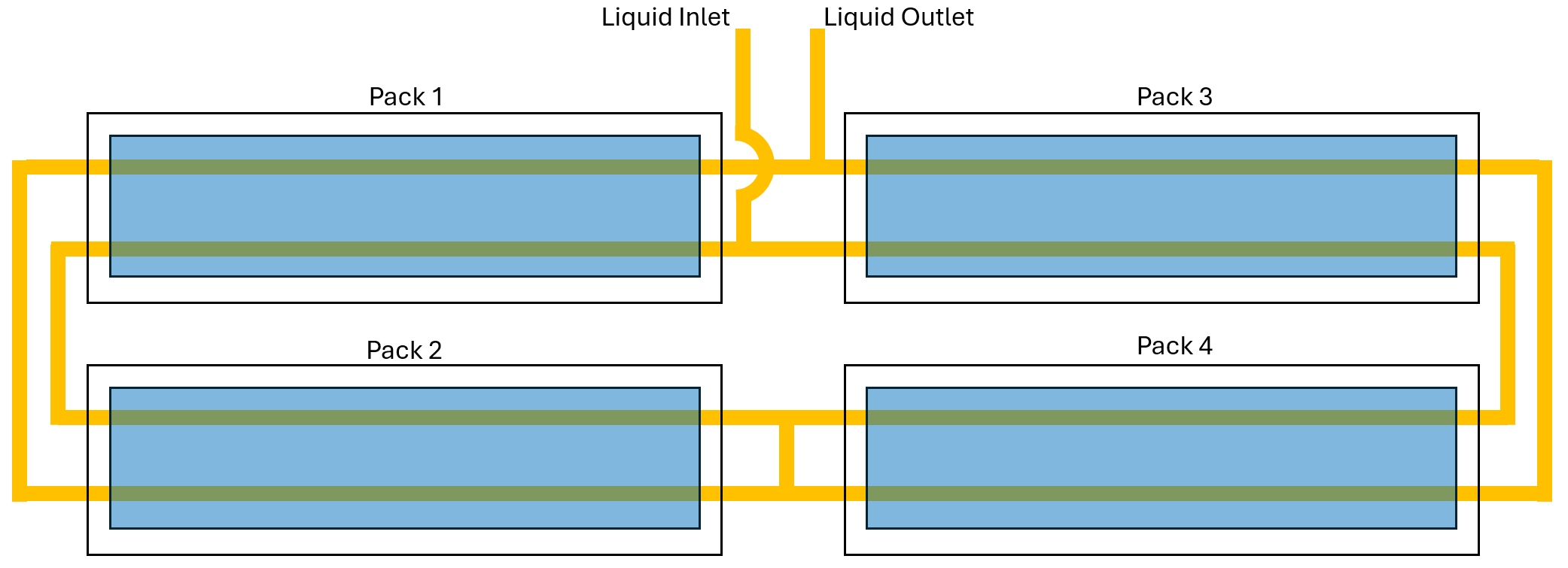
open_system('EVBatteryThermalManagementSystem/Cold Plate/Individual Plates')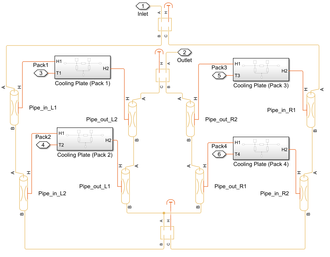
The integrated plate variant represents a single large cooling plate on which all the battery packs rest. As shown in this schematic, the plate is discretized using sixteen custom plate elements. For advanced modeling of cooling plates, see Connect Cooling Plate to Battery Blocks (Simscape Battery).
open_system('EVBatteryThermalManagementSystem/Cold Plate/Integrated Plate')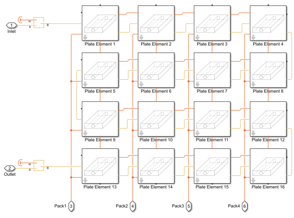
The model reuses these elements during compilation to increase the compilation speed. For more information, see Enable Component Reuse During Compilation.
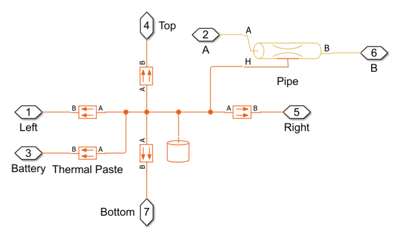
Each element consists of a Thermal Mass block and a Pipe (TL) block. Conductive Heat Transfer blocks model heat transfer from each element to neighboring elements and the battery.
open_system('EVBatteryThermalManagementSystem/Cold Plate/Integrated Plate/Plate Element 1','force')
Heating-Cooling Unit
In the heating-cooling unit the coolant either releases or absorbs heat. The unit has three subunits: a refrigerant system, a radiator, and a heater. The valve system distributes flows among these subunits. In cooling mode, the valve system allows flows only through the refrigerant system and the radiator, distributing flows between them for effective cooling. In heating mode, the valve system directs the coolant to flow only through the heater.
open_system('EVBatteryThermalManagementSystem/Heating-Cooling Unit')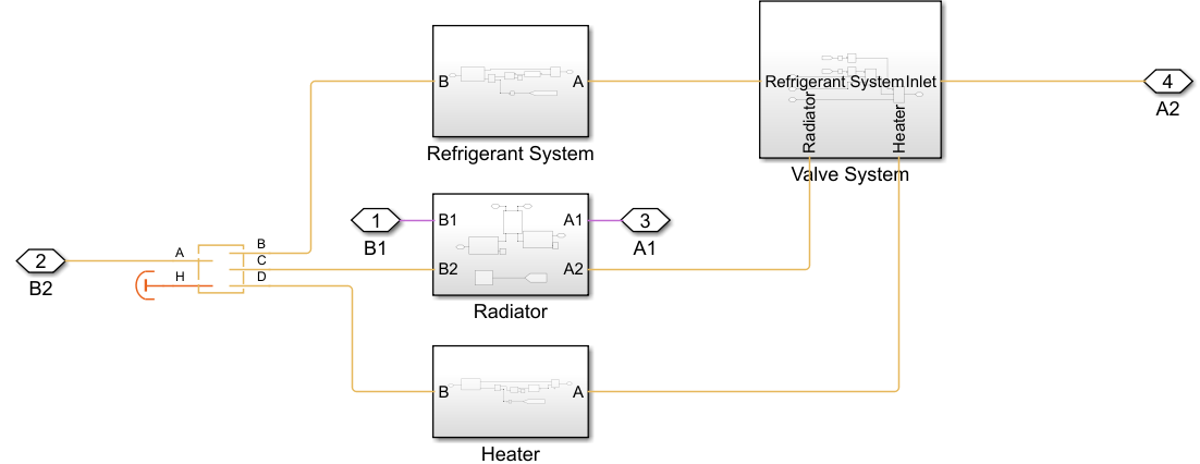
open_system('EVBatteryThermalManagementSystem/Heating-Cooling Unit/Valve System')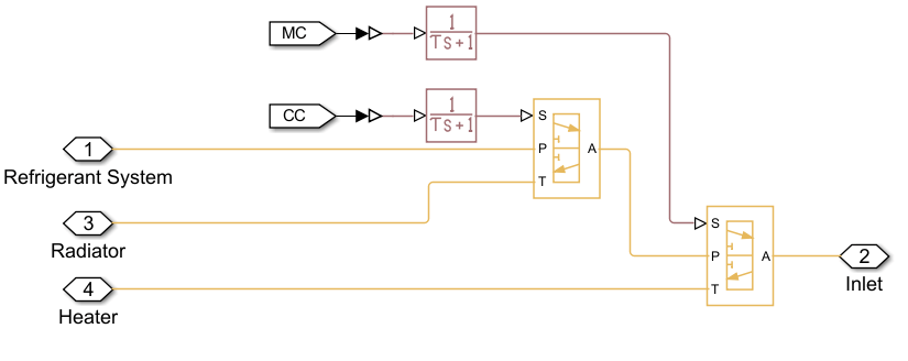
Drive Cycle Simulations
By default, the model uses the following conditions:
Battery target temperature = 20 °C
Environment temperature = Initial battery temperature = 30 °C
System cycle = FTP-75 drive cycle
Cold plate architecture = Individual plates
Run the model.
sim("EVBatteryThermalManagementSystem")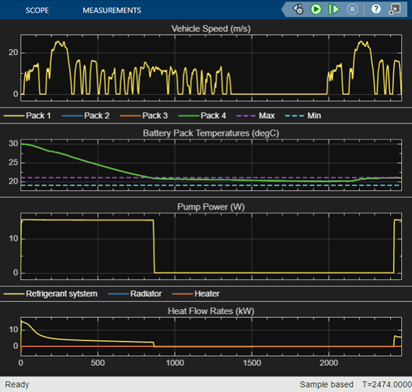
The refrigerant system operates to decrease the battery temperatures. The valve system does not direct flow into the radiator because the radiator cannot provide cooling because the environment temperature, 30 °C, is higher than the battery target temperature, 20 °C.
Run the simulation with a cold environment temperature, 5 °C. The initial battery temperature is identical to the environment temperature.
T_env  = 278;   % [K] Cold environment temperature
T_init = T_env; % [K] Initial system temperature
sim("EVBatteryThermalManagementSystem")
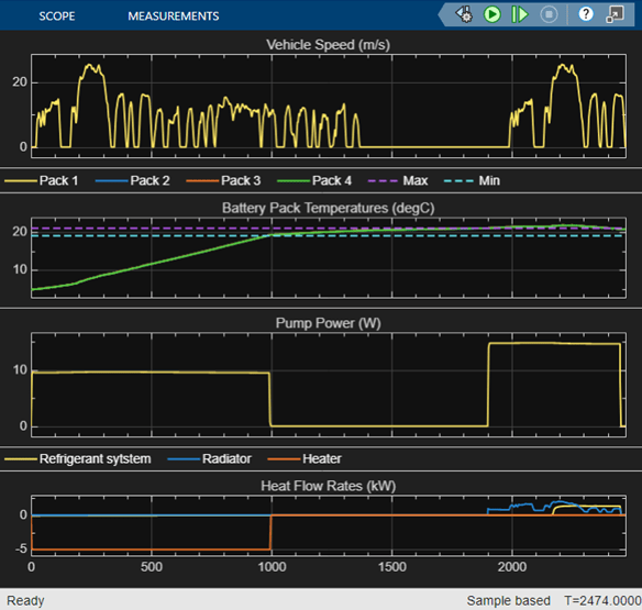
Initially, the heater provides heat, and later the radiator, through which cold ambient air passes, expels the system's heat into the environment.
Charge Cycle Simulations
Battery charging requires temperature control for efficient charging. Execute the simulation with the charge cycle at a moderate environment temperature.
set_param([bdroot '/System Inputs'], 'ActiveScenario', 'Charge_Cycle')
t_sim = 1600;         % [s]    Stop Time
battery.Qe_init = 25; % [A*hr] Initial cell charge deficit
T_env  = 288;         % [K]    Environment temperature
T_init = T_env;       % [K]    Initial system temperature
sim("EVBatteryThermalManagementSystem")
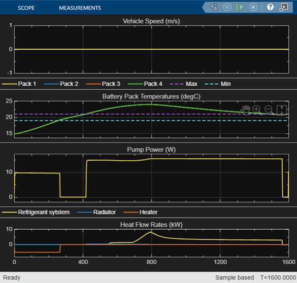
At first, the heater provides heating until the temperatures converge to the target value. After the heater stops operating, the temperature continues to rise due to heat generated by battery charging. The radiator initially removes the charging heat from the system by a small margin. Later the refrigerant system removes the charging heat for stronger cooling. Under high thermal loads, the valve for the cooling branches directs more coolant to flow through the refrigerant system rather than the radiator.
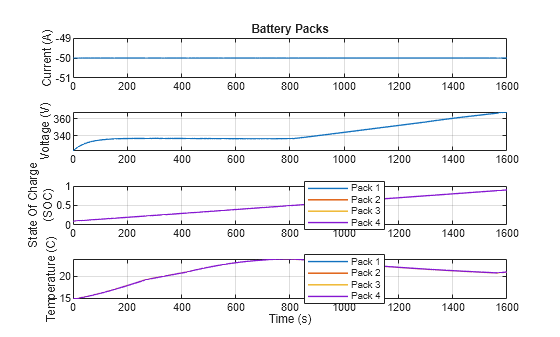
This figure shows the performance of a series of four lithium-ion battery packs.
EVBatteryThermalManagementSystemPlot1Battery
This figure shows heat flow rates in the system.
EVBatteryThermalManagementSystemPlot2Heat
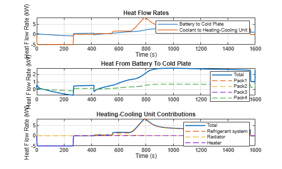
In the later period, the heat flow rate from the coolant to the heating-cooling unit is greater than the heat flow rate from the battery to the cold plate. The amount of this discrepancy corresponds to the pump power.
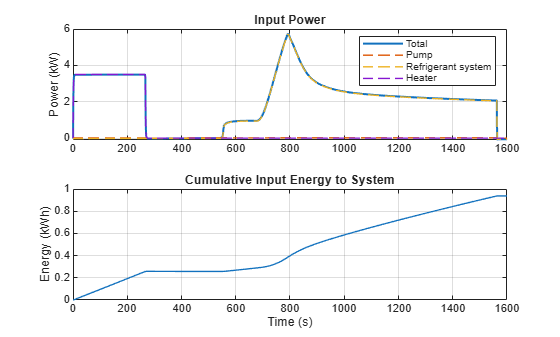
This figure shows the input power for the system. The plots assume both refrigerant and heater have the efficiency of 0.7.
EVBatteryThermalManagementSystemPlot3Energy
Simulate the same charge cycle with the integrated cold plate.
set_param([bdroot '/Cold Plate'], 'OverrideUsingVariant', 'IntegratedPlate')
sim("EVBatteryThermalManagementSystem")
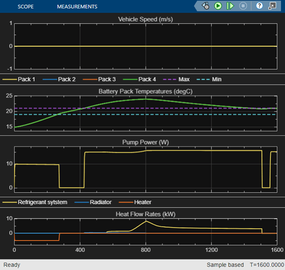
This figure shows an animation of the heat map of the integrated plate.
The target temperature is 20 °C, and the temperature distribution is fairly uniform at all times.
References
[1] Huria, Tarun, Massimo Ceraolo, Javier Gazzarri, and Robyn Jackey. "High fidelity electrical model with thermal dependence for characterization and simulation of high power lithium battery cells." In 2012 IEEE international electric vehicle conference, pp. 1-8. IEEE, 2012.