Vehicle HVAC System
This example models the heating and cooling system of a passenger car. The cabin is represented as a volume of moist air exchanging heat with the external environment. The blower drives moist air through the evaporator, blend door, and heater core before returning to the cabin. The blend door controls the amount of air flow through the heater core. The recirculation door controls whether air is brought in from the external environment or from within the cabin.
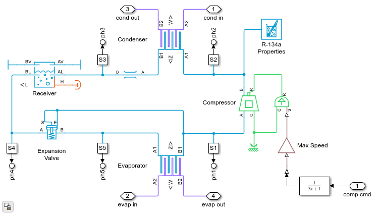
The evaporator and heater core are part of the refrigerant loop and coolant loop, respectively. The refrigerant loop is a typical R-134a vapor-compression refrigeration cycle with a compressor, a condenser, a liquid receiver, a thermostatic expansion valve, and an evaporator. The P-H Diagram block shows the thermodynamic states of the cycle during simulation.
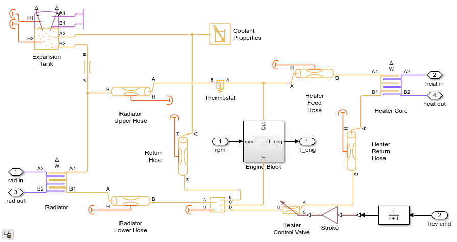
The coolant loop consists of an engine-driven pump which drives coolant through the coolant jacket to absorb heat and then through the radiator and/or the heater core to reject heat. The thermostat controls the amount of flow through the radiator to maintain the desired engine temperature. The heater control valve controls the amount of flow through the heater core to maintain the desired cabin heat. The expansion tank provides the volume for the coolant to thermally expand and contract.
The refrigerant loop and coolant loop are modeled in separate files via subsystem reference blocks. This makes it easier for different users to work on the refrigerant loop, the coolant loop, and the overall vehicle HVAC model independently. The refrigerant loop and coolant loop referenced subsystems include their own test harness models (requires Simulink® Test™) so that they can be simulated independently of the main vehicle HVAC model. For more information, see Create and Use Referenced Subsystems in Models.
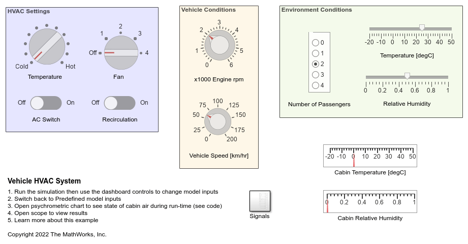
The vehicle HVAC model can be simulated in two modes: predefined inputs or manual inputs. When using predefined inputs, the HVAC settings and environment conditions are specified by Simulink source blocks. For the first 1800 s, the environment temperature is 30 degC and air conditioning is on. For the next 1800 s, the environment temperature is reduced to 10 degC, the air conditioning turns off, and the heater turns on. When using manual inputs, the HVAC settings and environment conditions can be adjusted at run time using the dashboard controls.
Model

Manual Inputs
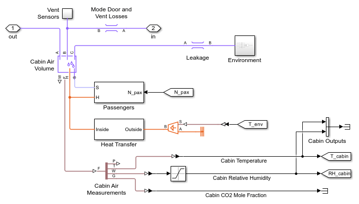
Cabin Subsystem
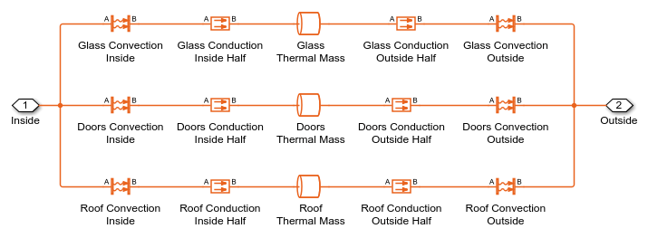
Heat Transfer Subsystem
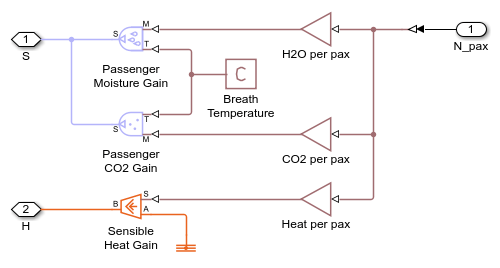
Passengers Subsystem
Coolant Loop Subsystem
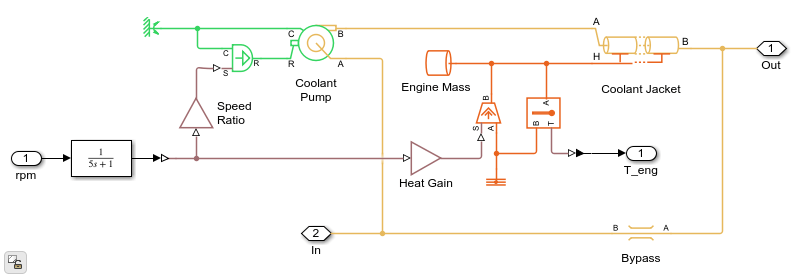
Engine Block Subsystem
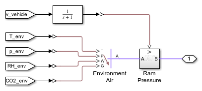
Intake Subsystem
Refrigerant Loop Subsystem
Simulation Results from Scopes
Simulation Results from Simscape Logging
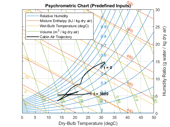
This figure shows a psychrometric chart for the moist air inside the cabin. It is based on the ASHRAE Psychrometric Chart No. 1 and is used to convey thermodynamic properties of moist air, such as dry-bulb temperature, wet-bulb temperature, relative humidity, humidity ratio, and enthalpy. When using predefined inputs, the trajectory of the state of the cabin moist air during simulation is plotted on the chart. When using manual inputs, the state of the cabin moist air is continuously updated during run-time.

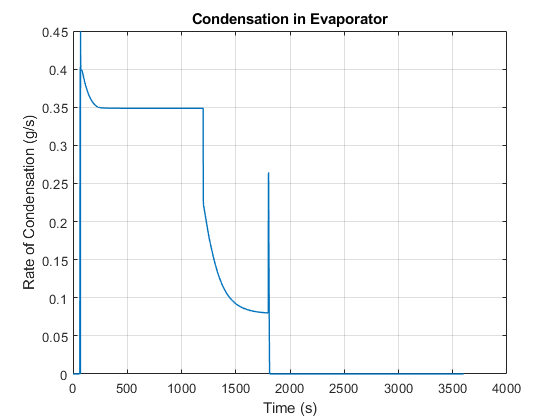
This plot shows rate of condensation in the evaporator when the air conditioning is turned on.
This plot shows the contributions to power consumption in the vehicle HVAC system, as well as the coefficient of performance of the refrigeration loop. Note that the air conditioning is turned off at 1800 seconds.