Cross-Junction (IL)

Libraries:
Simscape /
Fluids /
Isothermal Liquid /
Pipes & Fittings
Description
The Cross-Junction (IL) block represents a four-way junction in an isothermal liquid network. The block abstracts the fluid interactions depending on the direction of flow at each port, where ports A and C are the main line and ports B and D are the branch line.
Mass and Momentum Balance
The block conserves mass such that
where ṁi is the mass flow rate for a given port, i.
The block determines which coefficient and vector element to use, then computes the pressure difference to conserve momentum such that
where:
is the average fluid density.
pi is the pressure for a given port, i.
p1 is the pressure at node 1.
ki is the flow coefficient that the block assigns to a given port, i. The Loss coefficient model parameter specifies the block method used to calculate ki.
Ii is the fluid inertia for a given port, i.
The block calculates the inertia for each port as
where Amain is the value of the Main line area (A,C) parameter and Aside is the value of the Branch line area (B,D) parameter.
Idel'chik Correlation Coefficient Model
When you set the Loss coefficient model parameter to
Idel'chik correlation, the block calculates the pipe
loss coefficients according to [1].
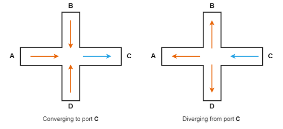
The Idel'chik model only supports flow converging to port C or
flow diverging from port C. To achieve expected results, orient
the block appropriately to the expected flow configuration of the model fluid
network.
The block treats the junction as symmetrical about both the horizontal and vertical planes such that AA = AC is the value of the Main line area (A,C) parameter, and AB = AD is the value of the Branch line area (B,D) parameter, where AA,B,C,D is the area of the corresponding port.
In the case of a prohibited flow geometry, you can control the block behavior by
using the Report when flow configuration is invalid parameter.
If the Report when flow configuration is invalid parameter is
None or Warning, the model
continues to run in the prohibited flow configuration, but the results may not be
correct.
When the flow is converging to port C, the loss coefficients for ports A and C are
The converging flow loss coefficients for ports B and D are
When the flow diverges from port C, the loss coefficients for ports A and C are
The diverging flow loss coefficients for ports B and D are
where A'=1 when and A'≈0.9 when . The block smooths the transition between A' = 1 and A' = 0.9 using a hyperbolic tangent function.
According to [1], these loss coefficients are only applicable for diverging
flow when the ratio of the side branch diameter to the main branch diameter is
less than or equal to 2/3. However, the expected error for
ratios above 2/3 is generally low enough that the block
continues to use the above loss coefficients.
Custom Cross-Junction
When you set the Loss coefficient model parameter to
Custom, the block uses the user-defined loss
parameters to describe the pipe loss coefficient at each port.
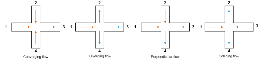
For a custom cross-junction, the block allows four configurations diverging flow, converging flow, perpendicular flow, and colliding flow:
Diverging flow — Flow enters at node 1 and exits at nodes 2, 3, and 4.
Converging flow — Flow enters at nodes 1, 2, and 4 and exits at node 3.
Perpendicular flow — Flow enters at nodes 1 and 2 and exits at nodes 3 and 4.
Colliding flow — Flow enters at nodes 1 and 3 and exits at nodes 2 and 4.
This figure demonstrates these configurations.
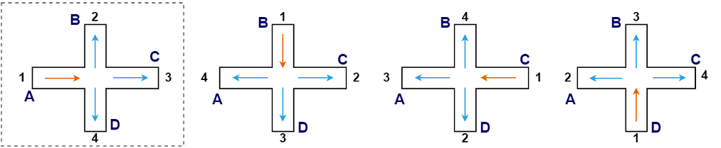
The block treats the junction as symmetrical about both the horizontal and vertical planes such that A1 = A3 and A2 = A4, where A1,2,3,4 is the area of the corresponding port in the figure. Using this symmetry, the block assumes the loss coefficients from 1 to 2 and from 1 to 4 are identical during diverging, converging, and colliding flow.
During simulation, the block continually checks the direction of flow at each port and compares the result to the four possible flow configurations. When the block determines the flow configuration, it adjusts the node that each port corresponds to. For example, when the block experiences diverging flow where the fluid enters at port A and exits at ports B, C, and D, it assigns node 1 to port A as in the first panel of the figure. The other panels show the assigned nodes for diverging flow entering at ports other than A.
For the custom cross-junction, all four flow configurations can occur in the same block during a simulation. You only need to supply parameters for each condition that the block experiences. If you use two-element vectors to specify the flow coefficients, the block uses the first or second element depending on whether node 1 aligns with the main line or the branch line. The first element corresponds to node 1 at port A or C, and the second element corresponds to node 1 at port B or D.
This table describes the conditions and coefficients for each operational mode used to determine the loss coefficients.
| Flow Scenario | ṁA | ṁB | ṁC | ṁD | kA | kB | kC | kD |
|---|---|---|---|---|---|---|---|---|
| Diverging from node A | >ṁthresh | <-ṁthresh | <-ṁthresh | <-ṁthresh | 0 | kdiv,turning,main | kdiv,straight,main | kdiv,turning,main |
| Diverging from node B | <-ṁthresh | >ṁthresh | <-ṁthresh | <-ṁthresh | kdiv,turning,side | 0 | kdiv,turning,side | kdiv,straight,side |
| Diverging from node C | <-ṁthresh | <-ṁthresh | >ṁthresh | <-ṁthresh | kdiv,straight,main | kdiv,turning,main | 0 | kdiv,turning,main |
| Diverging from node D | <-ṁthresh | <-ṁthresh | <-ṁthresh | >ṁthresh | kdiv,turning,side | kdiv,straight,side | kdiv,turning,side | 0 |
| Converging to node A | <-ṁthresh | >ṁthresh | >ṁthresh | >ṁthresh | 0 | kconv,turning,main | kconv,straight,main | kconv,turning,main |
| Converging to node B | >ṁthresh | <-ṁthresh | >ṁthresh | >ṁthresh | kconv,turing,side | 0 | kconv,turing,side | kconv,straight,side |
| Converging to node C | >ṁthresh | >ṁthresh | <-ṁthresh | >ṁthresh | kconv,straight,main | kconv,turning,main | 0 | kconv,turning,main |
| Converging to node D | >ṁthresh | >ṁthresh | >ṁthresh | <-ṁthresh | kconv,turing,side | kconv,straight,side | kconv,turing,side | 0 |
| Perpendicular with main entry A | >ṁthresh | >ṁthresh | <-ṁthresh | <-ṁthresh | 0 | kperp,turning in,main | kperp,straight,main | kperp,turning out,main |
| Perpendicular with main entry B | <-ṁthresh | >ṁthresh | >ṁthresh | <-ṁthresh | kperp,turning out,side | 0 | kperp,turning in,side | kperp,turning straight,side |
| Perpendicular with main entry C | <-ṁthresh | <-ṁthresh | >ṁthresh | >ṁthresh | kperp,straight,main | kperp,turning out,main | 0 | kperp,turning in,main |
| Perpendicular with main entry D | >ṁthresh | <-ṁthresh | <-ṁthresh | >ṁthresh | kperp,turning in,side | kperp,turning straight,side | kperp,turning out,side | 0 |
| Colliding from main to branch | >ṁthresh | <-ṁthresh | >ṁthresh | <-ṁthresh | 0 | kcoll,turning,main | kcoll,straight,main | kcoll,turning,main |
| Colliding from branch to main | <-ṁthresh | >ṁthresh | <-ṁthresh | >ṁthresh | kcoll,turning,side | 0 | kcoll,turning,side | kcoll,straight,side |
| Stagnant | – | – | – | – | 1 or last valid | 1 or last valid | 1 or last valid | 1 or last valid |
The flow is stagnant when the mass flow rate conditions do not match any defined flow scenario. The block uses these parameters to calculate the flow coefficients:
kdiv,straight,main and kdiv,straight,side are the first and second elements of the Diverging flow straight loss coefficient parameter, respectively.
kdiv,turning,main and kdiv,turning,side are the first and second elements of the Diverging flow turning loss coefficient parameter, respectively.
kconv,straight,main and kconv,straight,side are the first and second elements of the Converging flow straight loss coefficient parameter, respectively.
kconv,turning,main and kconv,turning,side are the first and second elements of the Converging flow turning loss coefficient parameter, respectively.
kperp,straight,main and kperp,straight,side are the first and second elements of the Perpendicular flow straight loss coefficient parameter, respectively.
kperp,turning in,main and kperp,turning in,side are the first and second elements of the Perpendicular flow straight loss coefficient parameter, respectively.
kperp,turning out,main and kperp,turning out,side are the first and second elements of the Perpendicular flow straight loss coefficient parameter, respectively.
kcoll,straight,main and kcoll,straight,side are the first and second elements of the Colliding flow straight loss coefficient parameter, respectively.
kcoll,turning,main and kcoll,turning,side are the first and second elements of the Colliding flow turning loss coefficient parameter, respectively.
Ports
Conserving
Parameters
References
[1] Idel’chik, I. E. Handbook of hydraulic resistance: Coefficients of local resistance and of friction. Jerusalem: Israel Program for Scientific Translations, 1966.