IIR Filter
Note
The Filter Design HDL Coder™ product will be discontinued in a future release. Instead, you can model hardware behavior and generate HDL code by using the DSP HDL IP Designer (DSP HDL Toolbox) app, or the DSP HDL Toolbox™ System objects or blocks. The app, objects, and blocks provide algorithms with hardware-friendly control signals and architecture options. To generate HDL code from these algorithms, you must also have the HDL Coder™ product.
For an IIR filter that supports HDL code generation, use the dsphdl.BiquadFilter (DSP HDL Toolbox) object and generate code using HDL Coder tools. For an example that uses the dsphdl.BiquadFilter (DSP HDL Toolbox) to design a DC blocker for hardware, see Generate HDL Code for IIR Filter (DSP HDL Toolbox).
Note
In R2024b, The dsp.BiquadFilter object issues a warning
and will be removed in a future release.
Create a Folder for Your Tutorial Files
Set up a writable working folder outside your MATLAB® installation
folder to store files that will be generated as you complete your
tutorial work. The tutorial instructions assume that you create the
folder hdlfilter_tutorials on drive C.
Design an IIR Filter in Filter Designer
This tutorial guides you through the steps for designing an IIR filter, generating Verilog code for the filter, and verifying the Verilog code with a generated test bench.
This section guides you through the procedure of designing and creating a filter for an IIR filter. This section assumes that you are familiar with the MATLAB user interface and the Filter Designer.
Start the MATLAB software.
Set your current folder to the folder you created in Create a Folder for Your Tutorial Files.
Start the Filter Designer by entering the
filterDesignercommand in the MATLAB Command Window. The Filter Design & Analysis Tool appears.
In the Filter Design & Analysis Tool, set these filter options.
Option Value Response Type HighpassDesign Method IIR ButterworthFilter Order Specify order:5Frequency Specifications Units:
HzFs:
48000Fc:
10800Click Design Filter. The Filter Designer creates a filter for the specified design. This message appears in the Filter Designer status bar when the task is complete.
Designing Filter... Done
For more information on designing filters with the Filter Designer, see Use Filter Designer with DSP System Toolbox Software.
Quantize the IIR Filter
You should quantize filters for HDL code generation. To quantize your filter,
Open the IIR filter design you created in Design an IIR Filter in Filter Designer if it is not already open.
Click the Set Quantization Parameters button
 in the left-side toolbar. The Filter
Designer displays the Filter arithmetic list in the
bottom half of the window.
in the left-side toolbar. The Filter
Designer displays the Filter arithmetic list in the
bottom half of the window.
Select
Fixed-pointfrom the list. The Filter Designer displays the first of three tabbed panels of the window.
Use the quantization options to test the effects of various settings on the performance and accuracy of the quantized filter.
Select the Filter Internals tab and set Rounding mode to
Floorand Overflow Mode toSaturate.Click Apply. The quantized filter appears as follows.
For more information on quantizing filters with the Filter Designer, see Use Filter Designer with DSP System Toolbox Software.
Configure and Generate VHDL Code
After you quantize your filter, you are ready to configure coder options and generate VHDL® code. This section guides you through starting the Filter Design HDL Coder UI, setting options, and generating the VHDL code and a test bench for the IIR filter you designed and quantized in Design an IIR Filter in Filter Designer and Quantize the IIR Filter.
Start the Filter Design HDL Coder UI by selecting Targets > Generate HDL in the Filter Designer tool. The Filter Designer displays the Generate HDL tool.
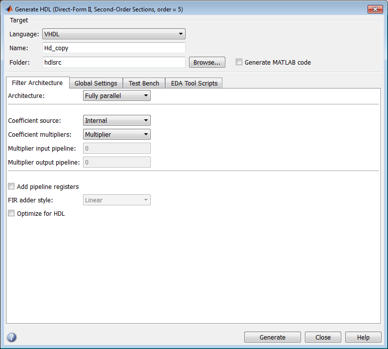
In the Name text box of the Target pane, type
iir. This option names the VHDL entity and the file that contains the VHDL code for the filter.Select the Global settings tab of the UI. Then select the General tab of the Additional settings section.
In the Comment in header text box, type
Tutorial
- IIR Filter
. The coder adds the comment to the end of the header comment block in each generated file.Select the Ports tab. The Ports pane appears.

Clear the check box for the Add output register option. The Ports pane now appears as in this figure.

Select the Advanced tab. The Advanced pane appears.
Select the Use 'rising_edge' for registers option. The Advanced pane now appears as in this figure.

Click the Test Bench tab in the Generate HDL tool. In the File name text box, replace the default name with
iir_tb. This option names the generated test bench file.
In the Generate HDL tool, click Generate to start the code generation process. When code generation completes, click OK to close the window.
The coder displays these messages in the MATLAB Command Window as it generates the filter and test bench VHDL files:
### Starting VHDL code generation process for filter: iir
### Starting VHDL code generation process for filter: iir
### Generating: H:\hdlsrc\iir.vhd
### Starting generation of iir VHDL entity
### Starting generation of iir VHDL architecture
### Second-order section, # 1
### Second-order section, # 2
### First-order section, # 3
### HDL latency is 1 samples
### Successful completion of VHDL code generation process for filter: iir

### Starting generation of VHDL Test Bench
### Generating input stimulus
### Done generating input stimulus; length 2172 samples.
### Generating Test bench: H:\hdlsrc\filter_tb.vhd
### Please wait ...
### Done generating VHDL Test Bench
### Starting VHDL code generation process for filter: iir
### Starting VHDL code generation process for filter: iir
### Generating: H:\hdlsrc\iir.vhd
### Starting generation of iir VHDL entity
### Starting generation of iir VHDL architecture
### Second-order section, # 1
### Second-order section, # 2
### First-order section, # 3
### HDL latency is 1 samples
### Successful completion of VHDL code generation process for filter: iir
As the messages indicate, the coder creates the folder
hdlsrcunder your current working folder and places the filesiir.vhdandiir_tb.vhdin that folder.Observe that the messages include hyperlinks to the generated code and test bench files. By clicking these hyperlinks, you can open the code files directly into the MATLAB Editor.
The generated VHDL code has these characteristics:
VHDL entity named
iir.Registers that use asynchronous resets when the reset signal is active high (1).
The table shows the default names of the ports.
VHDL Port Name Input filter_inOutput filter_outClock input clkClock enable input clk_enableReset input resetAn extra register for handling filter input.
Clock input, clock enable input, and reset ports are of type
STD_LOGICand data input and output ports are of typeSTD_LOGIC_VECTOR.Coefficients are named
coeff, wherennis the coefficient number, starting with 1.Type-safe representation is used when zeros are concatenated:
'0' & '0'...Registers are generated with the
rising_edgefunction rather than the statementELSIF clk'event AND clk='1' THEN.The postfix
'_process'is appended to process names.
The generated test bench:
Is a portable VHDL file.
Forces clock, clock enable, and reset input signals.
Forces the clock enable input signal to active high.
Drives the clock input signal high (1) for 5 nanoseconds and low (0) for 5 nanoseconds.
Forces the reset signal for two cycles plus a hold time of 2 nanoseconds.
Applies a hold time of 2 nanoseconds to data input signals.
For an IIR filter, applies impulse, step, ramp, chirp, and white noise stimulus types.
Explore the Generated VHDL Code
Get familiar with the generated VHDL code by opening and browsing through the file
iir.vhd in an ASCII or HDL simulator editor.
Open the generated VHDL filter file
iir.vhd.Search for
iir. This line identifies the VHDL module, using the value you specified for the Name option in the Target pane. See step 2 in Configure and Generate VHDL Code.Search for
Tutorial. This section is where the coder places the text you entered for the Comment in header option. See step 5 in Configure and Generate VHDL Code.Search for
HDL Code. This section lists coder options you modified in Configure and Generate VHDL Code.Search for
Filter Settings. This section of the VHDL code describes the filter design and quantization settings as you specified in Design an IIR Filter in Filter Designer and Quantize the IIR Filter.Search for
ENTITY. This line names the VHDL entity, using the value you specified for the Name option in the Target pane. See step 2 in Configure and Generate VHDL Code.Search for
PORT. ThisPORTdeclaration defines the filter's clock, clock enable, reset, and data input and output ports. The ports for clock, clock enable, reset, and data input and output signals are named with default character vectors.Search for
CONSTANT. This code defines the coefficients. They are named using the default naming scheme,coeff_, wherexm_sectionnxisaorb,mis the coefficient number, andnis the section number.Search for
SIGNAL. This code defines the signals of the filter.Search for
input_reg_process. ThePROCESSblock nameinput_reg_processincludes the defaultPROCESSblock postfix'_process'. This code reads the filter input from an input register. Code for this register is generated by default. In step 7 in Configure and Generate VHDL Code, you cleared the Add output register option, but left the Add input register option selected.Search for
IF reset. This code asserts the reset signal. The default, active high (1), was specified. Also note that thePROCESSblock applies the default asynchronous reset style when generating VHDL code for registers.Search for
ELSIF. This code checks for rising edges when the filter operates on registers. Therising_edgefunction is used as you specified in the Advanced pane of the Generate HDL tool. See step 10 in Configure and Generate VHDL Code.Search for
Section 1. This section is where second-order section 1 data is filtered. Similar sections of VHDL code apply to another second-order section and a first-order section.Search for
filter_out. This code drive the filter output data.
Verify the Generated VHDL Code
This section explains how to verify the generated VHDL code for the IIR filter with the generated VHDL test bench. This tutorial uses the Siemens® ModelSim™ simulator as the tool for compiling and simulating the VHDL code. You can use other HDL simulation tool packages.
To verify the filter code, complete these steps.
Start your simulator. When you start the Siemens ModelSim simulator, a screen display similar to this appears.

Set the current folder to the folder that contains your generated VHDL files. For example:
cd hdlsrc
If desired, create a design library to store the compiled VHDL entities, packages, architectures, and configurations. In the Siemens ModelSim simulator, you can create a design library with the
vlibcommand.vlib work
Compile the generated filter and test bench VHDL files. In the Siemens ModelSim simulator, you compile VHDL code with the
vcomcommand. These commands compile the filter and filter test bench VHDL code.vcom iir.vhd vcom iir_tb.vhd
This figure shows the command sequence and informational messages displayed during compilation.

Load the test bench for simulation. The procedure for loading the test bench varies depending on the simulator you are using. In the Siemens ModelSim simulator, you load the test bench for simulation with the
vsimcommand. For example:vsim work.iir_tb
This figure shows the results of loading
work.iir_tbwith thevsimcommand.
Open a display window for monitoring the simulation as the test bench runs. In the Siemens ModelSim simulator, use this command to open a wave window and view the results of the simulation as HDL waveforms.
add wave *
This wave window appears.

To start running the simulation, issue the start simulation command for your simulator. For example, in the Siemens ModelSim simulator, you can start a simulation with the
runcommand.This figure shows the
run -allcommand being used to start a simulation.
As your test bench simulation runs, watch for error messages. If error messages appear, interpret them as they pertain to your filter design and the HDL code generation options you selected. Determine whether the results are expected based on the customizations you specified when generating the filter VHDL code.
Note
The warning messages that note
Time: 0 nsin the preceding display are not errors and you can ignore them.The failure message that appears in the preceding display is not flagging an error. If the message includes the text
Test
Complete
, the test bench has run to completion without encountering an error. TheFailurepart of the message is tied to the mechanism that the coder uses to end the simulation.
This wave window shows the simulation results as HDL waveforms.
Select a Web Site
Choose a web site to get translated content where available and see local events and offers. Based on your location, we recommend that you select: United States.
You can also select a web site from the following list
Americas
- América Latina (Español)
- Canada (English)
- United States (English)
Europe
- Belgium (English)
- Denmark (English)
- Deutschland (Deutsch)
- España (Español)
- Finland (English)
- France (Français)
- Ireland (English)
- Italia (Italiano)
- Luxembourg (English)
- Netherlands (English)
- Norway (English)
- Österreich (Deutsch)
- Portugal (English)
- Sweden (English)
- Switzerland
- United Kingdom (English)
Asia Pacific
- Australia (English)
- India (English)
- New Zealand (English)
- 中国
- 日本Japanese (日本語)
- 한국Korean (한국어)