Cosimulation of HDL Code with HDL Simulators
Generating HDL Cosimulation Blocks for Use with HDL Simulators
The coder supports generation of Simulink® HDL Cosimulation blocks. You can use the generated HDL Cosimulation blocks to cosimulate your filter design using Simulink with an HDL simulator. To use this feature, you must have an HDL Verifier™ license.
The generated HDL Cosimulation blocks are configured to conform to the port and data type interface of the filter selected for code generation. By connecting an HDL Cosimulation block to a Simulink model in place of the filter, you can cosimulate your design with the desired HDL simulator.
To generate HDL Cosimulation blocks:
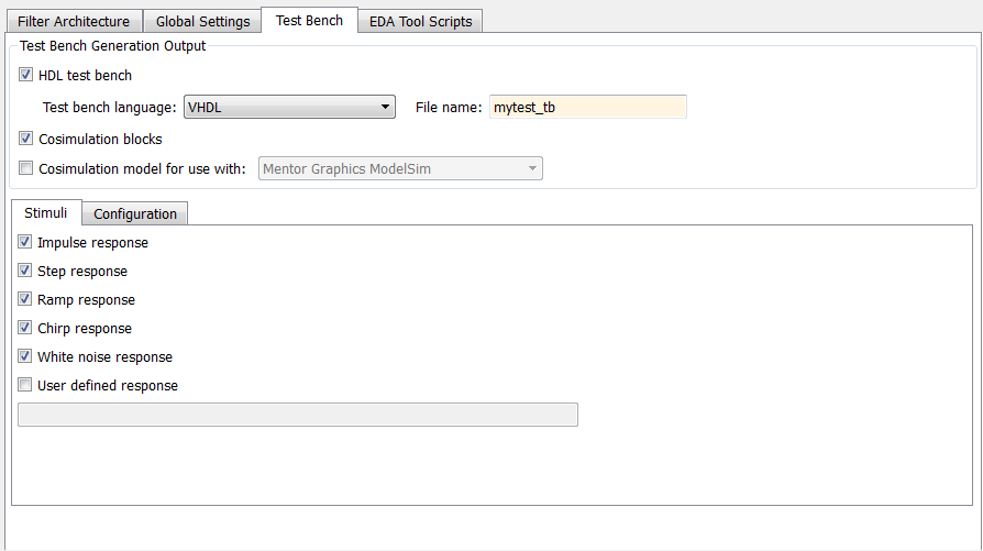
Select the Test Bench pane in the Generate HDL tool.
Select the Cosimulation blocks option.
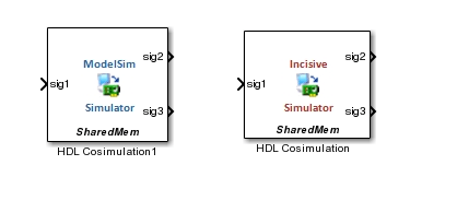
When this option is selected, the coder generates and opens a Simulink model that contains an HDL Cosimulation block for each supported HDL simulator.
If you want to generate HDL Cosimulation blocks only (without generating HDL test bench code), clear HDL test bench.
This figure shows both HDL test bench and Cosimulation blocks selected.
In the Generate HDL tool, click Generate to generate HDL and test bench code.
In addition to the usual code files, the coder generates a Simulink model containing an HDL Cosimulation block for each HDL simulator supported by HDL Verifier.
The generated model is untitled and exists in memory only. Be sure to save it to a destination folder if you want to preserve the model and blocks for use in future sessions.
To configure HDL Cosimulation block parameters, such as timing, latency, and data types, see Define HDL Cosimulation Block Interface (HDL Verifier).
Command-Line Alternative: Use the generatehdl function with the
property GenerateCosimBlock to generate HDL Cosimulation blocks.
Generating a Simulink Model for Cosimulation with an HDL Simulator
Note
To use this feature, you must have an HDL Verifier license.
The coder generates a Simulink model, that runs a Simulink simulation of your filter design, and also a cosimulation of your design with an HDL simulator. The model compares the outputs of the Simulink filter with the results of the HDL simulation.
The generated model includes:
A behavioral model of the filter design, realized in a Simulink subsystem. The subsystem implements the filter design using basic blocks such as adders and delays.
A corresponding HDL Cosimulation block. The coder configures this block to cosimulate the filter design using Simulink with either of these HDL simulators.
Siemens® ModelSim™
Cadence Incisive®
Test input data, calculated from the test bench stimulus you specify. The coder stores the test data in the model workspace variable
inputdata. A From Workspace block routes test data to the filter subsystem and HDL Cosimulation blocks.A Scope block that lets you observe and compare the test input signal with the outputs of the Filter block and the HDL cosimulation. The scope also shows the difference (error) between these two outputs.
Generating the Model
Generation of a cosimulation model requires registered inputs and/or outputs (see Limitations). Before generating the model, make sure that your model meets this requirement, as follows:
Select the Global Settings pane the Generate HDL tool.
In the Global Settings pane, click the Ports tab. Port options appear.
Select both of these options.
Add input register
Add output register
To generate the model:
In the Generate HDL tool, configure other code generation and test bench parameters as required by your design.
Select the Test bench pane of the Generate HDL tool.
Select the Cosimulation model for use with: option. Selecting this option enables the adjacent drop-down menu, where you can select
Mentor Graphics ModelSimorCadence Incisive.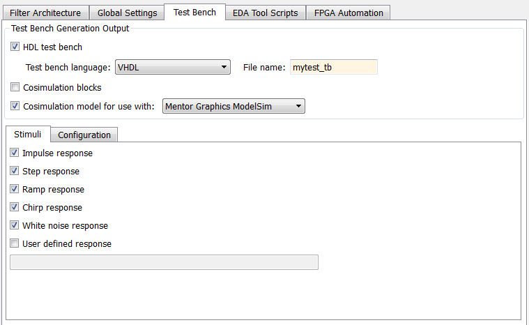
Using the drop-down menu, select which type of HDL Cosimulation block you want in the generated model. Select either
Mentor Graphics
                                ModelSim
(the default) orCadence Incisive.In this figure, the cosimulation model type is
Mentor Graphics
                                ModelSim
, and the stimulus signal is White noise response.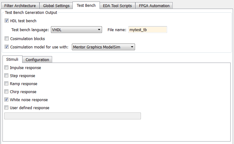
In the Generate HDL tool, click Generate to generate HDL and test bench code.
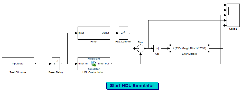
In addition to the usual code files, the coder generates and opens a Simulink model. This figure shows the model generated from the coder configuration shown in the previous step.
The generated model is untitled and exists in memory only. Be sure to save it to a destination folder if you want to preserve the model and blocks for use in future sessions.
To configure HDL Cosimulation block parameters, such as timing, latency, and data types, see Define HDL Cosimulation Block Interface (HDL Verifier).
Details of the Generated Model
The generated model contains these blocks.
Test Stimulus: This From Workspace block routes test data in the model workspace variableinputdatato the filter subsystem and HDL Cosimulation blocks.Filter: This subsystem realizes a behavioral model of the filter design.HDL Cosimulation: This block cosimulates the generated HDL code. The table HDL Cosimulation Block Settings describes how the coder configures the cosimulation block parameters.Reset Delay: The Tcl commands specified in theHDL Cosimulationblock apply the reset signal. Reset is high at 0 ns and low at 22 ns (before the third rising clock edge). The Simulink simulation starts feeding the input at 0, 10, 20 ns. TheReset Delayblock adds a delay such that the first sample is available to the RTL simulation when it is ready after the reset is applied.HDL Latency: This delay represents the difference between the latency of the RTL simulation and the Simulink behavioral block.Error: Computes the difference between the outputs of theFilterblock and theHDL Cosimulationblock.Abs: Absolute value of the error computation.Error margin:: Indicator comparing the absolute value of the error with the test bench error margin value (see Setting an Error Margin for Optimized Filter Code).Scope: Displays the input signal, outputs from theFilterblock and theHDL Cosimulationblocks, and the difference (if one exists) between the two.Start HDL Simulatorbutton: Starts your HDL cosimulation software.
HDL Cosimulation Block Settings
| Pane | Settings |
|---|---|
Ports | Port names: same as the names in the generated code for the filter. Input/Output data types:
Input sample
time: Output sample time: Same as Simulink fixed step size. |
Clocks | Clock port name: same as the name in the generated code for the filter. Active clock edge:
Period: same as the Simulink sample time. |
Timescales | 1 second in Simulink corresponds to 1 tick in the HDL simulator |
Connection | Connection Mode: Connection Method:
|
Tcl (Pre-simulation commands) |
force /Hlp/clk_enable 1; force /Hlp/reset 1 0 ns, 0 22 ns; puts ----------------------------------------- puts "Running Simulink Cosimulation block."; puts [clock format [clock seconds]] |
Tcl (Post-simulation commands) |
force /Hlp/reset 1 puts [clock format [clock seconds]] |
Generated Model Settings. The generated model has these nondefault settings:
Solver:
Discrete (no continuous states).Solver Type:
Fixed-step.Stop Time:
Ts * StimLen, whereTsis the Simulink sample time andStimLenis the stimulus length.Sample Time Colors: enabled
Port Data Types: enabled
Hardware Implementation: ASIC/FPGA
Limitations
A cosimulation that runs without encountering errors requires that outputs from the generated HDL code are synchronous with the clock. Before generating code, make sure that both of these options are selected:
Add input register
Add output register
If you do not select either of these options, the coder terminates model generation with an error. However, test bench code generation is completed.
The coder does not support generation of a cosimulation model when the target language is Verilog and data of type double is generated.
Command-Line Alternative
Use the generatehdl function, passing
in one of these values for the property GenerateCosimModel.
generatehdl(filtSysObj,'InputDataType',numerictype(1,16,15), ...
    'GenerateCosimModel','Incisive');
generatehdl(filtSysObj,'InputDataType',numerictype(1,16,15), ...
    'GenerateCosimModel','ModelSim');
Select a Web Site
Choose a web site to get translated content where available and see local events and offers. Based on your location, we recommend that you select: United States.
You can also select a web site from the following list
Americas
- América Latina (Español)
- Canada (English)
- United States (English)
Europe
- Belgium (English)
- Denmark (English)
- Deutschland (Deutsch)
- España (Español)
- Finland (English)
- France (Français)
- Ireland (English)
- Italia (Italiano)
- Luxembourg (English)
- Netherlands (English)
- Norway (English)
- Österreich (Deutsch)
- Portugal (English)
- Sweden (English)
- Switzerland
- United Kingdom (English)
Asia Pacific
- Australia (English)
- India (English)
- New Zealand (English)
- 中国
- 日本Japanese (日本語)
- 한국Korean (한국어)