Workflow Advisor
R2026bDescription
Use the Workflow Advisor to convert MATLAB® functions into High-Level Synthesis (HLS) code for FPGA and ASIC implementation.
The tool guides you through a step-by-step process to prepare, validate, and generate either HLS (SystemC™/SynthesizableC++) or HDL (VHDL® or Verilog®) code. You can use this tool to transition from MATLAB algorithm design to deployable hardware code. For more information on the MATLAB HDL Workflow Advisor, see Workflow Advisor.
With the Workflow Advisor, you can:
Create a project or open an existing HDL Coder™ project.
Perform fixed-point conversion.
Generate synthesizable HLS code and corresponding test benches.
Verify the numerical behavior of generated HLS code with an HLS test bench.
Generate a customized IP core.
Customize target and synthesis tool settings.
Integrate with third-party FPGA tools for synthesis and implementation.
Package and deploy your design to supported hardware platforms.
Generate a programming file and download it to the target device.
Note
Workflow Advisor is not available in MATLAB Online™.
Open the Workflow Advisor
Type
hdlcoderin the MATLAB Command Window.Alternatively, in the MATLAB Toolstrip, on the Apps tab, select HDL Coder.
In the Create HDL Coder Project dialog box, specify a project Name and Folder, then click OK to open the HDL Workflow Advisor.
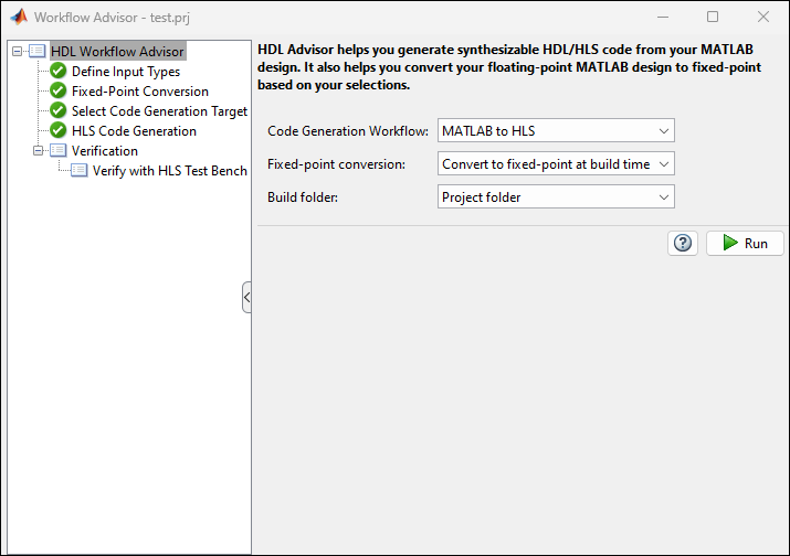
In the HDL Workflow Advisor task, select the Code Generation Workflow.
In the Define Input Types task, add the design and test bench files:
For MATLAB Function, click Browse and select the MATLAB design file.
For MATLAB Test Bench, click the + button and select the MATLAB test bench file.
Click Run. The HDL Workflow Advisor runs the test bench to infer the input data types of the MATLAB design.
Note
Sometimes HDL Coder cannot determine whether the entry-point functions in your project are suitable for HDL code generation. The most likely reason is that HDL Coder is unable to find the entry-point files. Verify that your current working folder is set to the folder that contains your entry-point files. If it is not, either make this folder your current working folder or add the folder containing these files to the MATLAB path.
Examples
Parameters
HDL Workflow Advisor
Specify the type of code to generate from your MATLAB code:
MATLAB to HDL— Generate HDL code in VHDL or Verilog.MATLAB to HLS— Generate HLS code inSystemCorSynthesizableC++.
Specify whether to convert the floating-point data in your design:
Convert to fixed-point at build
                                                  time
— Use the Fixed-Point Conversion tool to convert floating-point types to fixed-point during code generation.Keep original types— Retain the data types in the original MATLAB algorithm.
Choose where to store generated build files:
Project folder— Store build files in the project folder.Specified folder— Choose a custom location.
Enter a folder name in which to store the build files, or click Browse to select an existing folder.
Dependencies
To enable this parameter, set Build folder to Specified folder.
Define Input Types
Specify the entry-point MATLAB function for code generation. Click Browse to select the design function.
Specify the test script or function that calls the MATLAB function for validation.
Use the Add a file button  to add a new test bench and the Remove selected file
button
to add a new test bench and the Remove selected file
button  to remove the selected test bench.
Fixed-Point Conversion
Use the Fixed-Point Conversion tool to convert the floating-point data types in your DUT to fixed-point. For more information on how to use the Fixed-Point Conversion tool, see Automated Fixed-Point Conversion.
Dependencies
To enable this task, set Fixed-Point Conversion to
Convert to fixed-point at build time.
Select Code Generation Target
The HDL Workflow Advisor makes different options and downstream tasks available based on the workflow you select.
Generic ASIC/FPGA— Generate SystemC/Synthesizable C++ code suitable for High-Level Synthesis using HLS tools.IP Core Generation— Generate a custom IP core and integrate it with embedded software in an embedded system integration project.
Choose the hardware platform for which to generate the custom IP core. Your list of options might differ based on the products and support packages you have installed.
Generic Xilinx Platform— Generates an IP core for integration with Xilinx FPGA hardware.Get more— Install an available HDL Coder support package if your hardware platform is not listed.
Dependencies
To enable this parameter, set Workflow to
IP Core Generation.
Choose the synthesis tool that matches your target hardware and development
environment. You do not need to specify a synthesis tool if you want to generate generic
HLS code. When you set Workflow to IP Core
Generation, the setting you choose for Platform determines the settings
that appear in this parameter.
No synthesis tool specified— Use when you do not need to target a specific hardware device.Cadence Stratus HLS— Targets supported hardware using the Cadence® Genus synthesis tool.Xilinx Vitis HLS— Targets AMD® hardware. Requires specification of the Chip family and Device parameters.Xilinx Vivado— Targets AMD hardware using the Vivado® tool.Xilinx Vivadois available only for IP Core generation. Requires specification of the Chip family, Device, Package, and Speed parameters.
If no synthesis tool appears in the list, ensure the tool is installed and its path is set up correctly. Then click Refresh list in the HDL Workflow Advisor.
Choose your target device chip family to use for the synthesis tool. The options for this parameter depend on the setting of the Synthesis tool parameter.
Dependencies
To enable this parameter, set Synthesis tool to a
setting other than No synthesis tool specified.
Choose the device to target for synthesis. This specification determines the specific hardware configuration that the synthesis tool uses during synthesis and implementation.
Dependencies
To enable this parameter, set Synthesis tool to a
setting other than No synthesis tool specified.
Choose the target device package to use for synthesis. This specification determines the physical form factor and pin configuration that the synthesis tool uses during synthesis and implementation.
Dependencies
To enable this parameter, set Synthesis tool, Chip family, and Device to a synthesis tool, chip family, and device that supports different physical package types for synthesis.
Choose the speed grade of the target device to use for synthesis. This specification determines the timing characteristics that the synthesis tool uses during synthesis and implementation.
Dependencies
To enable this parameter, set Synthesis tool, Chip family, and Device to a synthesis tool, chip family, and device that supports different speed grades for synthesis.
Specify the target clock frequency, in MHz, for the generated HDL design. Use this value to configure the clock module and timing constraints during synthesis and implementation.
Select the predefined embedded system integration project into which HDL Coder inserts your generated IP core. The reference design defines the hardware and software environment for integrating and testing the IP core.
To create a reference design, see Register a Custom Reference Design.
Dependencies
To enable this parameter, set Workflow to IP Core Generation.
Enter a name for the generated IP core. The app uses this field to
name the IP core in the generated files. For example, if you
enter myFilter, the tool generates an IP core
named myFilter_ip.
If this field is empty, the tool uses the name of the top-level MATLAB function as the base name for the IP core.
Dependencies
To enable this parameter, set
Workflow to
IP Core
                                                Generation
.
Enter a version number or label for the generated IP core. The tool includes this value in the IP core metadata. Use this value to track changes across iterations.
Dependencies
To enable this parameter, set
Workflow to
IP Core
                                                Generation
.
Enter the IP core vendor name. The vendor name must not start with a numeric character
(for example, 23network is invalid), and must not contain whitespace
characters (for example, net work is invalid). The vendor name does not
need to include a domain suffix such as .com or .net.
You can specify the vendor name only when you set the Target
workflow to IP Core Generation and the
Synthesis tool to Xilinx Vivado.
Select how the processor and FPGA operate relative to each other during execution:
Free running— The processor and FPGA run independently without automatic synchronization.Coprocessing-blocking— HDL Coder generates synchronization logic so the processor waits for the FPGA to complete execution before continuing. Use this option when the FPGA execution time is short relative to the processor sample time.
Dependencies
To enable this parameter, set Workflow to IP Core Generation.
Note
To enable the Set Target Interface tab, in Select Code
Generation Target, set Workflow to IP Core
Generation.
Select Code Generation Target > Set Target Interface
Select the Set Target Interface task to see the fixed-point representation of the MATLAB design. The app generates this code using Fixed-Point Designer™.
The Ports table displays the properties of the input and output functions. Use this table to map these functions to I/O resources on the target device. The table contains these sections:
Inport – Lists input functions to the design
Outport – Lists output functions from the design
The app displays the function names and their data types in these sections. Use the Target Platform Interfaces and Bit Range / Address / FPGA Pin columns to map each function to a hardware interface and physical or logical resource on the target platform.
| Column Name | Description |
|---|---|
| Port Name | The name of the function in the MATLAB design. This field is read-only. |
| Data Type | The data type assigned to the function. This field is read-only. |
| Target Platform Interfaces | Specify the interface type on the target hardware platform. For example:
Available options depend on your Device selection. |
| Bit Range / Address / FPGA Pin | Specify the connection details for the selected interface type:
|
Dependencies
To enable this parameter, set Workflow to
IP Core
          Generation
.
The Build Log tab displays the detailed messages and status updates generated during the code generation process.
Dependencies
To enable this parameter, set Workflow to IP Core Generation.
HLS Code Generation > Target
Specify the HLS language for the generated code. When Synthesis tool is set to:
No synthesis tool specified– Target language is set toSystemC.Cadence Stratus HLS– Target language is set toSystemC.Xilinx Vitis HLS– Target language is set toSynthesizableC++.Xilinx Vivado– Target language is set toSynthesizableC++.
Dependencies
Synthesis tool Xilinx Vivado is only available when the
Workflow is IP Core
Generation.
Select this parameter to analyze your MATLAB design and ensure it is compatible for HLS code generation.
Select this parameter to generate an HTML report that provides traceability information and details about the generated HDL code.
Select this parameter to generate an HTML report that provides traceability information.
HLS Code Generation > Coding Style
Select this parameter to preserve comments from the original MATLAB code in the generated HLS code.
Select this parameter to include the original MATLAB source code as comments in the generated HLS code.
Select this parameter to include the current time and date in the header comments of each generated HLS file. This can help track when the code was generated for versioning or audit purposes.
Specify a comment to insert at the top of each generated HLS and test bench file. Use this to include author information, project details, or version notes.
Specify a prefix to prepend to the name of the generated DUT module in Verilog or SystemVerilog, or entity in VHDL. This helps customize naming to match project or organizational conventions.
Specify a string to append to the names of the real part of complex signals in the generated HLS code. This helps distinguish real and imaginary components when complex data types are split during code generation.
Specify a string to append to the names of the imaginary part of complex signals in the generated HLS code. This helps distinguish real and imaginary components when complex data types are split during code generation.
Specify a string to append to names of entities, signals, constants, or other MATLAB code elements that conflict with reserved words in the target HLS language. HDL Coder uses this postfix to ensure the generation of valid and synthesizable HLS code.
Select this parameter to create regions in the generated HLS code. Use these regions
to perform design space exploration using the HLS tools. The code generator stores the
generated region labels in the ml.tcl file when you set the synthesis
tool to Cadence Stratus HLS.
HLS Code Generation > Optimizations
Select this parameter to map all persistent array variables to RAM to reduce area.
Specify the minimum RAM size to begin mapping all persistent array variables and delays to block RAM. You can specify the minimum RAM mapping threshold either by using a single integer or by specifying the thresholds for the data:
To map persistent array variables to RAM when the RAM size is greater than this threshold, in bits, use a single integer. To calculate the total RAM size for persistent arrays, use this formula:
RAMSize = Array size * Word length * Complexity
Complexityis 2 for a complex data type or 1 for a real data type. To calculate the total RAM size for delays, use this formula:RAMSize = Delay length * Word length * Vector length * Complexity
To specify one threshold for the array size (for persistent arrays) or delay length (for delays), and one threshold for the word length or bit width of the data type, enter the thresholds in the format
MxN.For example, to specify a delay length of 500 cycles and word length of 50 bits, enter
500x50.Using a string of format
MxNthat specifies two thresholds to define the shape of the data to map to RAM, one for array size (for persistent arrays) or delay length (for delays) and one for word length or bit width of the data type.
Select this parameter to initialize all block RAM elements to zero for simulation.
Specify whether HDL Coder generates HLS code to handle integer overflow. Overflow saturates to either the minimum or maximum value the data type can represent.
This parameter only applies to MATLAB built-in integer data types. It does not apply to double, single, or fixed-point data types.
HLS Code Generation > Advanced
Specify whether to generate instantiable HLS code modules from functions.
Specify the array layout for HLS code generation.
Code replacement library name, specified as a character vector or string scalar. Use code replacement libraries to replace MATLAB functions and operators with custom C/C++ implementations in the generated HLS code.
Select this parameter to generate a report that shows which functions and operators in the generated code were replaced by the code replacement library.
Specify an additional Tcl file to include during synthesis. Use the browse button to navigate to and select the Tcl file. The Tcl file can contain additional synthesis constraints or commands for the synthesis tool.
HLS Code Generation > Code
Display the MATLAB DUT in the MATLAB Workflow Advisor.
Note
To enable the Verification tab, in Select Code Generation
Target, set Workflow to High Level
Synthesis.
Verify with HLS Test Bench > Output Settings
Specify whether to generate HLS test bench code from MATLAB test bench stimulus.
Specify whether to simulate the HLS DUT with the generated HLS test bench code with an HDL simulator.
Dependencies
To enable this parameter, Simulation tool must be set to a
value other than No simulation tool available on system
path.
Simulation tool to simulate the generated HLS test bench. After you set up your simulation tool, click Refresh list to make the tool available in the HDL Workflow Advisor.
Dependencies
Selecting Simulate generated test bench enables this option. The value of the Simulation tool depends on your selection of the Synthesis tool.
Verify with HLS Test Bench > Test Bench Options
Specify the method to use for the floating-point tolerance check of the generated code with respect to the floating-point DUT.
| Setting | Result |
|---|---|
Relative Error | HDL Coder checks for the floating-point tolerance of the native floating-point library or the floating-point target library that the DUT mapped to based on the relative error. |
ULP Error | HDL Coder checks for the floating-point tolerance of the native floating-point library or the floating-point target library that the DUT mapped to based on the ULP error. |
Specify the tolerance value to use for the Floating point tolerance check method. The default value for Tolerance Value changes depending on the value of the Floating point tolerance check parameter.
| Floating point tolerance check Value | Result |
|---|---|
Relative Error |
|
ULP Error |
|
Note
To enable the Synthesis and Analysis tab, in Select Code
Generation Target, set Workflow to High Level
Synthesis and select the Synthesis tool.
Synthesis and Analysis > Run Synthesis
Select this parameter to skip the Run Synthesis step.
Embedded System Integration > Create Project
Displays the third-party embedded system tool to use to create the IP core project.
HDL Coder determines the value for the Embedded system tool parameter based on the value of the Synthesis tool parameter.
Displays the name of the folder where the third-party synthesis tool generates and saves project files.
Embedded System Integration > Generate Software Interface
Select this parameter to skip the Generate Software Interface step.
Embedded System Integration > Build Embedded System
Select this parameter to generate the bitstream in a separate processes in parallel with your current MATLAB instance. If this option is disabled, you cannot use MATLAB until the build is finished.
Embedded System Integration > Program Target Device
Select this parameter to skip the Program Target Device step.
Specify the programming method for the target device.
Download— Copies the generated FPGA bitstream, Linux devicetree, and system initialization scripts to the SD card on the target board, and keeps the bitstream on the SD card persistently. This is the default method for SoC hardware platforms. To use this method, you do not require an Embedded Coder license. HDL Coder uses an SSH object to copy the bitstream to the SD card and reprogram the board. You can create the SSH object by specifying the IP Address, SSH Username, and SSH Password.Use the Download method because it programs the FPGA bitstream and loads the corresponding Linux devicetree before booting the Linux system. This method is more robust and does not result in a kernel panic or kernel hang on boot up. During the Linux reboot, the FPGA bitstream is reprogrammed from the SD card automatically.
JTAG— Uses a JTAG cable to program the target device. Use this method to program SoC platforms and standalone FPGA boards. JTAG is the default method for standalone FPGA boards that do not have an embedded ARM processor.For SoC devices, use the Download method instead. The JTAG mode programs the onboard FPGA directly without involving the ARM processor and does not update the Linux devicetree. This can crash the Linux system or result in a kernel panic when the bitstream does not match the devicetree.
Custom— Uses a custom programming method that you define in your own custom reference design. Use theCallbackCustomProgrammingMethodproperty of thehdlcoder.ReferenceDesignclass to register a function handle for the callback function that runs when you execute the Program Target Device task. To define your callback function, create a file that defines a MATLAB function and add the file to your MATLAB path. For more information, seeCallbackCustomProgrammingMethod.
Specify the IP address of the target board. HDL Coder uses this IP address to create an SSH connection to the board for programming.
Dependencies
To enable this parameter, set Programming method
to Download.
Specify the SSH username for connecting to the target board. HDL Coder uses this username to create an SSH connection to the board for programming.
Dependencies
To enable this parameter, set Programming method
to Download.
Specify the SSH password for connecting to the target board. HDL Coder uses this password to create an SSH connection to the board for programming.
Dependencies
To enable this parameter, set Programming method
to Download.

