Configure C Code Deployment Types for Model Hierarchy
When you develop a complex system by using Model-Based Design, models have different requirements for the resulting code to run on the target platform. A deployment type indicates how the generated code for a model interacts with the target platform and code generated from other models. The deployment type also indicates the role of a model in the system and determines the composition rules for using the model in a hierarchy with other models. You can set the deployment type of each model in a system by using the Embedded Coder app or the code mappings programmatic interface. The deployment types are:
Component — The top model from which the code generator produces code. The code generator produces a standalone algorithm that runs on the target platform. The component code exposes its interface to other components in the system and to platform services.
Subcomponent — A model reference that a component model uses. The generated code entry points are symbolically scoped to the parent component and are not exposed to the platform.
Automatic — Embedded Coder determines the deployment type based on the model hierarchy context.
Embedded Coder uses the deployment type of a model to map elements of the model to interfaces in the code interface configuration. This example shows you how to configure the deployment types for several models in a system and generate code to run on the target platform.
Set Up Test Harness and Model Hierarchy
The model RollAxisAutopilotHarness is a harness model that generates
test inputs for the component model RollAxisAutopilot. The harness model
is for simulation only. You generate code for the model
RollAxisAutopilot. For this example, you add a referenced model to the
RollAxisAutopilot model to represent a subcomponent in the generated
code.
Open the model
RollAxisAutopilotHarness. At the command line, enteropenExample("RollAxisAutopilotHarness").View the component model
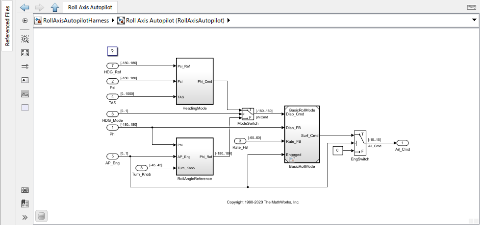
RollAxisAutopilotby double-clicking the Model block.Convert the subsystem
BasicRollModeto a referenced model. Right-click the Subsystem block and click Subsystem & Model Reference > Convert to > Referenced Model. The Model Reference Conversion Advisor opens. Click Convert.

The model hierarchy now contains these models:
RollAxisAutopilotHarness— The test harness that generates inputs forRollAxisAutopilot. You simulate this model. You do not generate code from this model.RollAxisAutopilot— The component model from which the code generator generates code for the target platform.BasicRollMode— A subcomponent for which the code generator produces code in the context of the component modelRollAxisAutopilot.
To generate code according to this hierarchy, configure the deployment types for these models.
Specify Deployment Types for the Models
You specify the deployment types of the models in one of these ways:
For each model, on the C Code tab, select the deployment type from the deployment type options. Select a deployment type from the Deployment Type menu or, for non-deployable models, select the Simulation only option from the Output menu.
Configure the models in a hierarchy by using the deployment configuration tool.
Use the code mappings programmatic interface.
For this example, use the deployment configuration tool and set the deployment types for the whole model hierarchy.
With the
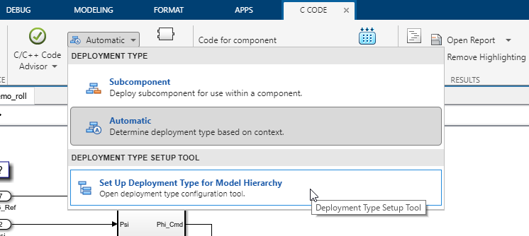
RollAxisAutopilotHarnessmodel open, open the Embedded Coder app.On the C Code tab, in the Prepare section, click the Automatic button. This button shows the deployment type for the model that is in the canvas. Automatic indicates that Embedded Coder determines the deployment type based on the model context.

From the Deployment Type menu, select Set Up Deployment Type for Model Hierarchy.
In the Set up deployment type for model hierarchy dialog box, expand the
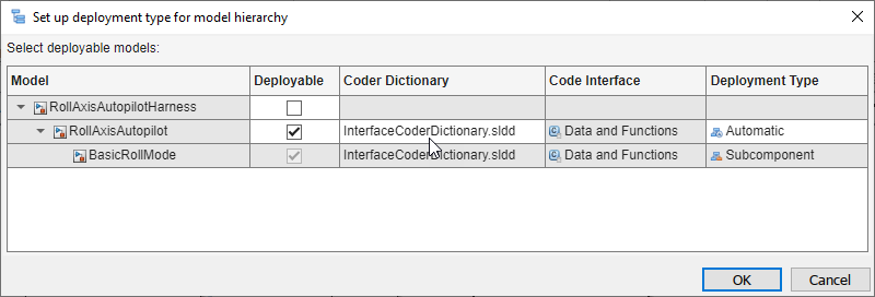
RollAxisAutopilotHarnessandRollAxisAutopilotmodels to see the model hierarchy.Specify the
RollAxisAutopilotHarnessmodel as simulation only. In the row for the model, clear the check box for the Deployable column. This configures the model for simulation only. The code generator does not produce code from this model.For the deployable models, the code interface configuration in the specified Coder Dictionary determines what deployment types are available.
Data interface configuration — the Automatic and Subcomponent data types are available.
Service interface configuration —the Component and Subcomponent data types are available.
For the
RollAxisAutopilotmodel, specify the Coder Dictionary as an .SLDD file that contains a coder dictionary with a data interface configuration.Specify the
RollAxisAutopilotmodel as an automatically determined deployment type. In the row for the model, in the Deployment Type column, double-click the box and from the drop-down select Automatic.Because
RollAxisAutopilotis a top model, theBasicRollModemodel is automatically configured as a subcomponent. For this model, the code generator produces subcomponent code, which is scoped to the component code forRollAxisAutopilot.
Click OK. On the C Code tab, the Code for component field shows the model for which you generate code.
Generate and Inspect Code
Generate code for the models. On the C Code tab, click
Build. The Code view displays the generated code next to the model.
To view code for a specific model, navigate to the model in the canvas. The Code view is
updated to show the code for the currently displayed model. If you navigate to a simulation
only model, such as RollAxisAutopilotHarness, the Code view continues to
show code from the component model.
View the code for the component model RollAxisAutopilot. This code
snippet shows some of the component interface that is generated for the
model.
#include "RollAxisAutopilot.h"
#include <math.h>
#include "rtwtypes.h"
#include "BasicRollMode.h"

/* Block signals and states (default storage) */
DW rtDW;

/* External inputs (root inport signals with default storage) */
ExtU rtU;

/* External outputs (root outports fed by signals with default storage) */
ExtY rtY;

/* Model step function */
void RollAxisAutopilot_step(void)
{
  /* local block i/o variables */
  real32_T rtb_BasicRollMode;
  real32_T rtb_FixPtUnitDelay1;

  /* Outputs for Atomic SubSystem: '<Root>/RollAngleReference' */
  /* UnitDelay: '<S3>/FixPt Unit Delay1' */
  rtb_FixPtUnitDelay1 = rtDW.FixPtUnitDelay1_DSTATE;
View the code for the subcomponent model BasicRollMode. This code
snippet shows some of the subcomponent interface that is generated for the
model.
#include "BasicRollMode.h"
#include "rtwtypes.h"

/* Disable for referenced model: 'BasicRollMode' */
void BasicRollMode_Disable(BasicRollMode_DW_f *localDW)
{
  /* Disable for DiscreteIntegrator: '<Root>/Integrator' */
  localDW->Integrator_DSTATE = localDW->Integrator;
}

/* Output and update for referenced model: 'BasicRollMode' */
void BasicRollMode(const real32_T *rtu_Disp_Cmd, const real32_T *rtu_Disp_FB,
                   const real32_T *rtu_Rate_FB, const boolean_T *rtu_Engaged,
                   real32_T *rty_Surf_Cmd, BasicRollMode_DW_f *localDW)
{
  real32_T rtb_Sum;
  real32_T u0;
  boolean_T rtb_NotEngaged;
To further customize the interface of the generated code, use the Code Mappings editor to map model element categories and individual model elements to code definitions. The Code Mappings editor shows code definitions that are available to the model based on the deployment type.