Code Mappings Editor — C
Associate model elements with code interface definitions
Description
The Code Mappings editor is a graphical interface where you associate model elements with code interface definitions. When you generate code from the model, the code generator applies the specified definitions to the code it generates from the associated model elements. Each model in a model reference hierarchy has its own code mappings.
Definitions can include:
Storage Classes — a storage class is a set of specifications for generating code from model data elements. It defines properties such as appearance and data types.
Function Customization Templates — a function customization template is a set of specifications for generating entry-point functions. It defines properties such as naming rules for function names and argument related identifiers.
Memory Sections — a memory section is a location in the computer memory, designated to contain specific code elements.
Service Interfaces — a service interface is set of specifications that defines a function prototype and a communication method. Each such interface corresponds to a function that is available to be invoked by the generated model code on the target platform. Tuning and measurement services are used by the generated model code to tune and measure model elements, respectively. Sender, receiver, and data transfer services are used for model elements communication. Timer services are used to obtain real-time information about the target platform clock. To learn more about service interfaces, see Service Interfaces.
The system target file you specify for your model, as well as other settings, determine which code interface definition types are available for configuration. The rest are determined automatically by the code generator.
With models configured to use the GRT system target file you can only configure storage class definitions. For each data element category, associate a default storage class to use throughout the model. Then, override the defaults, as needed, by specifying storage classes for individual data elements.
Models configured to use the ERT system target file can be configured with either data interface configuration or with service interface configuration.
With ERT models configured with data interface configuration, associate each category
of data elements with a default storage class to use throughout the model, and associate
each category of entry-point functions with a default function customization template to
use throughout the model. Then, override the default definitions, as needed, by
specifying storage classes for individual data elements and by specifying function
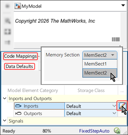
customization templates for individual entry-point functions. In some configurations,
you can explicitly specify a memory section on top of the specified storage class or
function customization template. This is possible when the definition of the specified
storage class or function customization template does not include a memory section. For
example, when you specify Default as the default storage
class for the model Inports category, as shown in this screenshot:
A service interfaces dictionary is an Embedded Coder® dictionary that contains service interface definitions, sorted by types. For each service type, one of the definitions is selected in the dictionary as the default service for the type. In addition, the dictionary contains definitions of storage classes, memory sections, and function customization templates. The dictionary specifies the default function customization template for each entry-point function category.
When an ERT model is linked to a shared Embedded Coder dictionary that defines service code interfaces, it means that the model is configured with service interfaces configuration. By default, the code generated from such models adheres to the default definitions, as specified in the dictionary. You can, however, use the Code Mappings editor to override the default code interface definitions, by associating individual entry-point functions with function customization templates from the dictionary and by associating individual model elements with services from the dictionary.
To configure model elements for code generation, use the Code Mappings editor tabs:
Data Defaults (only applicable for GRT models and ERT models with data interface configuration)
Function Defaults (only applicable for ERT models with data interface configuration)
Functions (only applicable for ERT models)
Inports
Outports
Data Transfers (only applicable for ERT models with service interface configuration)
Parameters
Data Stores
Signals/States
Depending on the type of element and the specified value, there could be
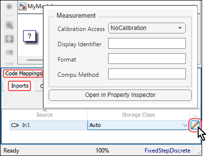
additional configurable code mapping properties you can set. To configure the additional
properties, select the pencil icon ![]() at the end of the row to open a dialog box. For
example, this screenshot shows the dialog box that opens when you click the pencil icon
for a root-level inport with Auto storage class.
at the end of the row to open a dialog box. For
example, this screenshot shows the dialog box that opens when you click the pencil icon
for a root-level inport with Auto storage class.
Signals, by default, are not added to the code mappings of the model. To configure a signal for code generation, add the signal to the model code mappings. To learn more about adding signals, see Add Signals to Model Code Mappings. To learn more about removing signals, see Remove Signals from Model Code Mappings.
Open the Code Mappings Editor — C
To open the editor, do one of the following:
In the model canvas of the Simulink® editor, click the perspective control in the lower-right corner and select Code. Then, click the Code Mappings tab.
Open the Simulink Coder™ app or the Embedded Coder app. Then, In the bottom left corner of the Simulink Editor window, click the Code Mappings tab.
Open the Simulink Coder app or the Embedded Coder app. Then, on the C Code tab of the Simulink toolstrip, in the prepare section, select Code Interface > Individual Element Code Mappings.
Examples
Configure Code Generation for Root-Level Inports and Outports With Simulink Coder
Configure code generation for the root-level Inport and Outport blocks throughout a model. Applying default configurations can save time, especially for large-scale models that use a significant amount of data. After applying default mappings, you can adjust mappings for individual data elements. To configure code generation for root-level In Bus Element blocks and Out Bus Element blocks use the same workflow as in the example.
Open the model
ConfigurationRapidPrototypingInterfaceby entering this command at the MATLAB® Command Window:openExample("ConfigurationRapidPrototypingInterface")Open the Simulink Coder app. The C Code tab includes the Code Mappings editor.
Configure the code generator to declare and define global variables for
inports and outports in generated files
ConfigurationRapidPrototypingInterface.h and
ConfigurationRapidPrototypingInterface.c.
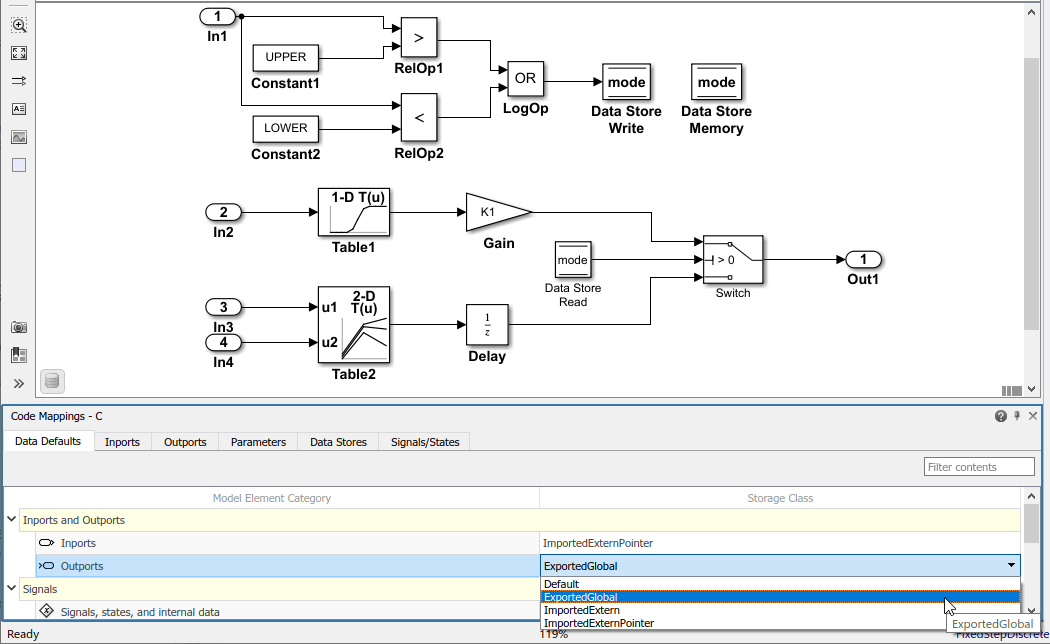
In the C Code tab, select Code Interface > Default Code Mappings.
In the Data Defaults tab, under Inports and Outports, select the row for Inports. Then, set the storage class to
ImportedExternPointer. Set the storage class for Outports toExportedGlobal. The editor updates the default storage class setting for the two selected data element categories.
In the Code Mappings editor, click the Inports tab. When the storage class is set to
Auto, the code generator might eliminate or change the representation of relevant code for optimization purposes. If optimizations are not possible, the code generator applies the model default configuration.Force the code generator to use the default configuration for inports, which is storage class
ImportedExternPointer. Press the Ctrl key and select the inports. For one of the selected inports, set the storage class toModel default: ImportedExternPointer. The editor updates the storage class setting for the selected inports.Force the code generator to use storage class
ExportedGlobalfor the model root-level outport. Click the Outports tab. Select the row forOut2. Then, set the storage class toModel default: ExportedGlobal.
To configure properties for individual data elements, for example, if you need
to override default configuration settings, use the tabs for the different data
element types. For this example, override the default storage class setting for
Inport block In1.
By default, the code generator names inport and outport variables based on the
Inport or Outport block name in the model.
When you configure data elements with a storage class setting other than
Auto, you can override that default setting for
individual elements by setting storage class property
Identifier. This property enables you to specify an
identifier for the code without modifying the model design.
For this example, set Identifier for the Inport and Outport blocks.
In the Code Mappings editor, click the Inports tab.
For
In1, set the storage class toImportedExtern.For each inport, select the row. Then, click the pencil icon
 and set the
Identifier property as follows:
and set the
Identifier property as follows:Set
In1toinput1.Set
In2toinput2.Set
In3toinput3.Set
In4toinput4.
Click Outports.
Select outport
Out1. Click the pencil icon and set the
Identifier property to
output.
Generate code and verify that the code generated for the Inport and Outport blocks appears as you expect. For example:
ConfigurationRapidPrototypingInterface_private.hincludes these declarations:/* Imported (extern) block signals */ extern real_T input1; /* '<Root>/In1' */ /* Exported data declaration */ /* Data with Imported storage (pointer) */ extern real_T *input2; /* '<Root>/In2' */ extern real_T *input3; /* '<Root>/In3' */ extern real_T *input4; /* '<Root>/In4' */
ConfigurationRapidPrototypingInterface.hincludes these declarations./* Data with Exported storage */ extern real_T output; /* '<Root>/Out1' */
This code fragment shows the variable that represents
In1,input1, being used in the generated entry-point step function./* Model step function */ void ConfigurationRapidPrototypingInterface_step(void) { /* DataStoreWrite: '<Root>/Data Store Write' incorporates: * Constant: '<Root>/Constant1' * Constant: '<Root>/Constant2' * Inport: '<Root>/In1' * Logic: '<Root>/LogOp' * RelationalOperator: '<Root>/RelOp1' * RelationalOperator: '<Root>/RelOp2' */ mode = ((input1 > 10.0) || (input1 < -10.0)); . . .
Configure Code Generation for Root-Level Inports and Outports With Embedded Coder Using a Data Code Interface
Configure code generation for the root-level Inport and Outport blocks throughout a model. Applying default configurations can save time, especially for large-scale models that use a significant amount of data. After applying default mappings, you can adjust mappings for individual data elements. To configure code generation for root-level In Bus Element and Out Bus Element blocks use the same workflow as in the example.
Open the model
RollAxisAutopilotby entering this command at the MATLAB Command Window:The current working directory contains these external code files.openExample("RollAxisAutopilot")roll_input_data.croll_input_data.hroll_heading_mode.croll_heading_mode.h
Open the Embedded Coder app.
Configure the code generator to:
Use header file
roll_input_data.hto declare the variables representing model Inport blocks.Represent variables for model Outport blocks as separate global variables.
Define output variables in
roll_output_data.cand declare them inroll_output_data.h.Configure names that the code generator uses for variables it produces in the code for Inport blocks.
In the C Code tab, select Code Interface > Default Code Mappings.
In the Data Defaults tab, under Inports and Outports, select the row for Inports. Then, set the storage class to
ImportFromFile.Click the pencil icon
and set Header
File to roll_input_data.h.Set the storage class for model element category Outports to
ExportToFile.Set Header File to
roll_output_data.hand Definition File toroll_output_data.c.
In the Code Mappings editor, click the Inports tab. The storage class for each inport is set to
Auto, which means that the code generator might eliminate or change the representation of relevant code for optimization purposes. If optimizations are not possible, the code generator applies the default configuration for inports.Force the code generator to use the default configuration for inports, storage class
ImportFromFilewith external header fileroll_input_data.h. Press the Ctrl key and select the inports. For one of the selected inports, set the storage class toModel default: ImportFromFile. The editor updates the storage class setting for the selected inports.
Override the default source location for inport variable
HDG_Mode. That variable is declared in the external file
roll_heading_mode.h.
In the Code Mappings editor, click the Inports tab.
Select the
HDG_Moderow.Set Storage Class to
ImportFromFile.Click the pencil icon
and set Header
File to roll_heading_mode.h.Configure the code generator to produce variable names in the code for the Inport blocks that match the variable names in external files
roll_input_data.handroll_heading_mode.h. On the Inports tab, select each Inport block, click the pencil icon and set
Identifier to the block name. When the storage
class is set to a value other than Auto, you can specify a value for the Identifier storage class property. If you leave the Identifier property empty, the code generator uses the name of the block or signal associated with the modeling element.
Include external source files roll_input_data.c and
roll_heading_mode.c in the code generation and build
process. Set the model configuration parameter Source files
to roll_input_data.c roll_heading_mode.c.
Save the model.
Generate code and verify that the code generated for the Inport and Outport blocks appears as you expect.
RollAxisAutopilot.hincludes these header files associated with storage classes:#include "roll_output_data.h" #include "roll_input_data.h" #include "roll_heading_mode.h"
roll_heading_mode.cincludesroll_heading_mode.hand defines variableHDG_Mode.#include "roll_heading_mode.h" boolean_T HDG_Mode;
roll_input_data.cdefines the variables declared inroll_input_data.h.#include "roll_input_data.h" boolean_T AP_Eng; real32_T HDG_Ref; real32_T Rate_FB; real32_T Phi; real32_T Psi; real32_T TAS; real32_T Turn_Knob;
roll_output_data.cincludes this exported data definition:real32_T Ail_Cmd;
roll_output_data.hincludes this exported data declaration:extern real32_T Ail_Cmd;
Configure Default Function Names for Entry-Point Functions With Embedded Coder Using a Data Code Interface
By default, the code generator uses the identifier naming rule
$R$N to name entry-point functions. $R is
the name of the top model. $N is the name of the function, for
example, initialize, step, and
terminate. To integrate generated code with existing external
code or to comply with naming standards or guidelines, you can adjust the default
naming rule. This example shows how to add the text string
myproj_ as a prefix to $R$. Adjusting the
default naming rule can save time, especially for multirate models for which the
code generator produces a unique step function for each
rate.
Open the model
MultirateMultitaskingby entering this command at the MATLAB Command Window:openExample("MultirateMultitasking")Open the Embedded Coder app. The C Code tab opens on the Simulink Toolstrip. You can open the Code Mappings editor pane by selecting Code Mappings - Component Interface near the status bar.
Create a function customization template that defines the naming rule
myproj_$R$N.
Open the Embedded Coder Dictionary. In the C Code tab, select Code Interface > Embedded Coder Dictionary (Model).
In the Data Interface pane, select Function Customization Templates.
In the center pane, click Create.
In the right pane, specify Name as
myproj_FunctionTemplate.Specify Function Naming Rule as
myproj_$R$N.Close the Embedded Coder Dictionary.
In the C Code tab, select Code Interface > Default Code Mappings.
Click the Function Defaults tab.
For the Initialize/Terminate and Execution function categories, change the default function customization template from
Defaulttomyproj_FunctionTemplate.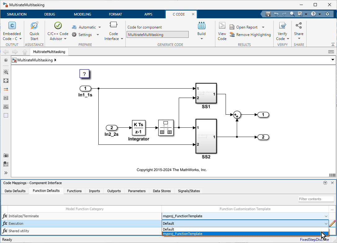
Save the model.
Generate code and verify the entry-point function names.
void myproj_MultirateMultitasking_step0(void) /* Sample time: [1.0s, 0.0s] */
{
  (rtM->Timing.RateInteraction.TID0_1)++;
  if ((rtM->Timing.RateInteraction.TID0_1) > 1) {
       rtM->Timing.RateInteraction.TID0_1 = 0;
  }

  if (rtM->Timing.RateInteraction.TID0_1 == 1) {
      rtDW.RateTransition = rtDW.RateTransition_Buffer0;
  }
      rtY.Out2 = 2.0 * rtDW.RateTransition + rtU.In1_1s;
      rtY.Out1 = (3.0 * rtDW.RateTransition + rtU.In1_1s) * 5.0 + rtY.Out2;
}

/* Model step function for TID1 */
void myproj_MultirateMultitasking_step1(void) /* Sample time: [2.0s, 0.0s] */
{
  rtDW.RateTransition_Buffer0 = rtDW.Integrator_DSTATE;
  rtDW.Integrator_DSTATE += 2.0 * rtU.In2_2s;
}

void myproj_MultirateMultitasking_initialize(void)
{
  /* (no initialization code required) */
}

void myproj_MultirateMultitasking_terminate(void)
{
  /* (no terminate code required) */
}
Customize Individual Entry-Point Functions With Embedded Coder Using a Data Code Interface
For your model, you can customize the names of most entry-point functions and the
arguments of execution functions, such as step functions and Simulink functions. This example shows how to customize the entry-point
functions for the model RollAxisAutopilot.
Open the model
RollAxisAutopilotby entering this command at the MATLAB Command Window:The current working directory contains these external code files.openExample("RollAxisAutopilot")roll_input_data.croll_input_data.hroll_heading_mode.croll_heading_mode.h
Open the Embedded Coder app. The C Code tab opens on the Simulink Toolstrip. You can open the Code Mappings editor pane by selecting Code Mappings - Component Interface near the status bar.
In the C Code tab, select Code Interface > Individual Element Code Mappings. The Code Mappings editor opens with the Functions tab selected.
Customize the name of the step (execution) function, with Source
Periodic:D1. In the Function Name column, enter the nameroll_run.Customize arguments of the
stepfunction. Open the configuration dialog box for thestepfunction by clicking the prototype hyperlink in the Function Preview column.Select Configure arguments for Step function prototype.
To open a table that displays the default configurations for the arguments, click Get Default.
Customize the arguments:
From the C return argument drop-down list, select
Ail_Cmd.For each port, in the C Identifier Name field, remove the
arg_prefix from their default names.For the
HDG_ModeInport, from the C Type Qualifier drop-down list, selectPointer. In the C Identifier Name field change the name toHDG_Mode_Ptr
Click Apply and verify that the function prototype reflects the changes.
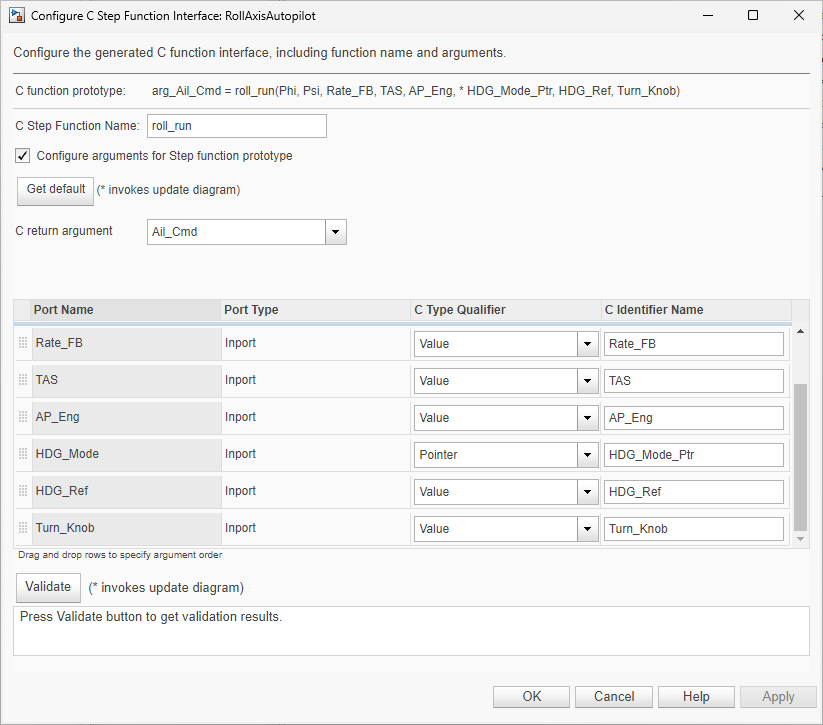
Validate the changes by clicking Validate.
Click OK.
Generate code.
Verify the updates in the generated C file
RollAxisAutopilot.c. To find the updatedstepfunction (roll_run), use the Search field.Select the
stepfunction to verify its prototype.real32_T roll_run(real32_T Phi, real32_T Psi, real32_T Rate_FB, real32_T TAS, boolean_T AP_Eng, boolean_T *HDG_Mode_Ptr, real32_T HDG_Ref, real32_T Turn_Knob)
Related Examples
- C Data Code Interface Configuration for Model Interface Elements
- Choose Data Configuration Approach
- Choose Storage Class for Controlling Data Representation in Generated Code
- Configure Default C Code Generation for Categories of Data Elements and Functions
- Configure Generated C Function Interface for Model Entry-Point Functions
- Customize Generated Entry Point C Functions
- Configure Signal Data for C Code Generation
Parameters
Data Defaults (only applicable for GRT models and ERT models with data interface configuration)
Category of model data elements for which to apply the code interface definitions. This table summarizes the model element categories.
| Model Element Category | Description | Programmatic Category Identifier |
|---|---|---|
| Inports | Root-level input ports of a model, such as Inport and In Bus Element blocks. | Inports |
| Outports | Root-level output ports of a model, such as Outport and Out Bus Element blocks. | Outports |
| Signals, states, and internal data | Data elements that are internal to the model, such as block output signals, discrete block states, data stores, and zero-crossing signals. | InternalData |
| Shared local data stores | Data Store Memory blocks that have the block parameter Share across model instances set. These data stores are accessible only in the model where they are defined. The data store value is shared across instances of the model. | SharedLocalDataStores |
| Global data stores | Data stores that are defined by a signal object in
the base workspace or in a data dictionary. Multiple
models in an application can use these data stores. To
view and configure these data stores in the Code
Mappings editor, click the Refresh
link to the right of the category name. Clicking this
link updates the model diagram. | GlobalDataStores |
| Model parameters | Parameters that are defined within a model, such as parameters in the model workspace. Excludes model arguments. | ModelParameters |
| External parameters | Parameters that you define as objects in the base
workspace or in a data dictionary. Multiple models in an
application can use these parameters. To view and
configure these parameters in the Code Mappings editor,
click the Refresh link to the right
of the category name. Clicking this link updates the
model diagram. | ExternalParameters |
| Model parameter arguments (only applicable for ERT models) | Parameters in the model workspace that you configure as model arguments. These parameters are exposed at the model block to enable each model instance to provide its own value. To specify a parameter as a model argument, select the Model Data Editor > Parameters > Argument check box. | ModelParameterArguments |
| Constants (only applicable for ERT models) | Constant-value block output and parameters that could not be inlined. These values are stored in variables for one of the following reasons.
| Constants |
To programmatically access the default value of a data
elements category, use the functions getDataDefault and setDataDefault with the code mappings
object of the model and the programmatic category identifier. For example,
to programmatically specify the default storage class of model inports as
ExportedGlobal, use the programmatic identifier of
inports,
Inports:
codeMapObj = coder.mapping.api.get(simulinkModel);
setDataDefault(codeMapObj,"Inports",StorageClass="ExportedGlobal");
Unspecified storage class (
Default). The code generator places the code for the category of data elements in standard structures, such asB_,ExtY_,ExtU_,DW_, andP_. See Data Structures in the Generated Code.Relevant predefined storage classes, such as
ExportedGlobal.Relevant storage classes in available packages, such as the storage class
ImportFromFile(only applicable for ERT models).Storage class defined in an Embedded Coder dictionary (only applicable for ERT models).
Default storage class definitions to use for generating code from model elements of the category. For more information, see Choose Storage Class for Controlling Data Representation in Generated Code.
To specify the value of this property, click the pencil icon
![]() at the end of the table entry to open a dialog-box that
contains the property.
at the end of the table entry to open a dialog-box that
contains the property.
When the specified storage class definition does not include a memory section, use the drop-down list to select a memory section to place the generated code in.
Function Defaults (only applicable for ERT models with data interface configuration)
Category of entry-point functions for which to apply the code interface definitions. This table summarizes the entry-point function categories.
| Model Function Category | Description | Programmatic Category Identifier |
|---|---|---|
| Initialize/Terminate | Entry-point functions for initialization and termination | InitializeTerminate |
| Execution | Entry-point functions for initiating execution and resets | Execution |
| Shared utility | Shared utility functions | SharedUtility |
To programmatically access the default value of a function
category, use the functions getFunctionDefault and setFunctionDefault with the code mappings object of the
model and the programmatic category identifier. For example, assume that you
defined the function customization template FT_01 in the
Embedded Coder dictionary of the model. To programmatically specify the
default function customization template of the initialization and
termination functions category as FT_01, use the
programmatic identifier of initialization and termination functions,
InitializeTerminate:
codeMapObj = coder.mapping.api.get(simulinkModel);
setFunctionDefault(codeMapObj,"InitializeTerminate",FunctionCustomizationTemplate="FT_01")
Default function customization template definitions to use for generating entry-point functions of the category.
To specify the value of this property, click the pencil icon
![]() at the end of the table entry to open a dialog-box that
contains the property.
at the end of the table entry to open a dialog-box that
contains the property.
When you specify Default as the function
customization template for the category, you can select a default memory
section, from those defined in the dictionary, to place generated
entry-point functions of the category.
Functions (only applicable for ERT models)
The identifier of the of entry-point function. For more information, see Types of Generated Entry-Point Functions.
Function customization template to use for generating the entry-point function code.
The name of the generated entry-point function.
Preview of the generated entry-point function prototype. To verify a prototype, review the prototype preview. To open a dialog box where you can customize the prototype, click the preview hyperlink. For more information, see Configure Default Settings for Functions.
To specify the value of this property, click the pencil icon
![]() at the end of the table entry to open a dialog-box that
contains the property.
at the end of the table entry to open a dialog-box that
contains the property.
Use the drop-down list to select a memory section for the generated entry-point function.
Since R2022b
To specify the value of this property, click the pencil icon
![]() at the end of the table entry to open a dialog-box that
contains the property.
at the end of the table entry to open a dialog-box that
contains the property.
Use the drop-down list to select a timer service, from those defined in the dictionary, to use with the generated entry-point function. For more information, see Configure Timer Service Interfaces.
Inports
Identifies a root-level Inport block or an In Bus
Element block (for example, InBus1.signal1)
in the model. If the element resolves to a data object, the Code Mappings
editor displays a resolve-to-signal-object icon to the right of the source
name and resolves the configuration based on whether the storage class
setting for the element is Auto. If the storage class is
Auto, the data element assumes the code configuration
that the data object specifies. The editor changes the display text in the
Storage Class column to From signal
object: followed by the name of the storage class of the data
object. If the storage class is not Auto, the data
element assumes the configuration that you specify in the Code Mappings
editor.
Storage class definitions to use for generating code from the inport. For more information, see Choose Storage Class for Controlling Data Representation in Generated Code.
To specify the value of this property, click the pencil icon
![]() at the end of the table entry to open a dialog-box that
contains the property.
at the end of the table entry to open a dialog-box that
contains the property.
Name for the variable that represents the inport in the generated code.
To specify the value of this property, click the pencil icon
![]() at the end of the table entry to open a dialog-box that
contains the property.
at the end of the table entry to open a dialog-box that
contains the property.
Select Calibration for the inport to enable the
calibration, or NoCalibration to view the value of the
inport and disable the calibration.
To specify the value of this property, click the pencil icon
![]() at the end of the table entry to open a dialog-box that
contains the property.
at the end of the table entry to open a dialog-box that
contains the property.
Optional display name of the inport for the measurement purpose in the calibration tool, which is different from the inport name in the Simulink model.
To specify the value of this property, click the pencil icon
![]() at the end of the table entry to open a dialog-box that
contains the property.
at the end of the table entry to open a dialog-box that
contains the property.
Special display format to be specified for measurement in the calibration
tool. This format specification overrules the display format specified in
Compu Method of the inport.
To specify the value of this property, click the pencil icon
![]() at the end of the table entry to open a dialog-box that
contains the property.
at the end of the table entry to open a dialog-box that
contains the property.
Name of the method for converting the ECU-internal value to a physical value for easy readability.
Since R2022b
To specify the value of this property, click the pencil icon
![]() at the end of the table entry to open a dialog-box that
contains the property.
at the end of the table entry to open a dialog-box that
contains the property.
Use the drop-down list to select a receiver service, from those defined in the dictionary, to use with the code generated from the inport. For more information, see Configure Sender and Receiver Service Interfaces for Model Inports and Outports.
Outports
Identifies a root-level Outport block or an Out Bus
Element block (for example, OutBus1.signal1)
in the model. If the element resolves to a data object, the Code Mappings
editor displays a resolve-to-signal-object icon to the right of the source
name and resolves the configuration based on whether the storage class
setting for the element is Auto. If the storage class is
Auto, the data element assumes the code configuration
that the data object specifies. The editor changes the display text in the
Storage Class column to From signal
object: followed by the name of the storage class of the data
object. If the storage class is not Auto, the data
element assumes the configuration that you specify in the Code Mappings
editor.
Storage class definitions to use for generating code from the outport. For more information, see Choose Storage Class for Controlling Data Representation in Generated Code.
To specify the value of this property, click the pencil icon
![]() at the end of the table entry to open a dialog-box that
contains the property.
at the end of the table entry to open a dialog-box that
contains the property.
Name for the variable that represents the outport in the generated code.
To specify the value of this property, click the pencil icon
![]() at the end of the table entry to open a dialog-box that
contains the property.
at the end of the table entry to open a dialog-box that
contains the property.
Select Calibration for the outport to enable the
calibration, or NoCalibration to view the value of the
outport and disable the calibration.
To specify the value of this property, click the pencil icon
![]() at the end of the table entry to open a dialog-box that
contains the property.
at the end of the table entry to open a dialog-box that
contains the property.
Optional display name of the outport for the measurement purpose in the calibration tool, which is different from the outport name in the Simulink model.
To specify the value of this property, click the pencil icon
![]() at the end of the table entry to open a dialog-box that
contains the property.
at the end of the table entry to open a dialog-box that
contains the property.
Special display format to be specified for measurement in the calibration
tool. This format specification overrules the display format specified in
Compu Method of the outport.
To specify the value of this property, click the pencil icon
![]() at the end of the table entry to open a dialog-box that
contains the property.
at the end of the table entry to open a dialog-box that
contains the property.
Name of the method for converting the ECU-internal value to a physical value for easy readability.
Since R2022b
To specify the value of this property, click the pencil icon
![]() at the end of the table entry to open a dialog-box that
contains the property.
at the end of the table entry to open a dialog-box that
contains the property.
Use the drop-down list to select a sender service, from those defined in the dictionary, to use with the code generated from the outport. For more information, see Configure Sender and Receiver Service Interfaces for Model Inports and Outports.
Data Transfers (only applicable for ERT models with service interface configuration)
Since R2022b
Identifies a signal line that connects two blocks that result in callable entry-point functions in the generated code. To learn more about callable entry-point functions, see Model Code Interfaces.
Data transfer service interface to use for code generation, specified as
one of the service interfaces defined in the Embedded Coder Dictionary of the model. Within the target environment, the
callable entry-point functions transfer data between them by calling the
specified data transfer service of the target platform. To use the default
data transfer service of the dictionary, specify Dictionary
default. To configure a data transfer service interface, you
must attach an Embedded Coder Dictionary that defines the service interface configuration to
the model. For more information, see Configure Data Transfer Service Interfaces for Data Transfer Signals.
Parameters
Identifies a parameter in the model. If the element resolves to a data
object, the Code Mappings editor displays a resolve-to-parameter-object icon
to the right of the source name and resolves the configuration based on
whether the storage class setting for the element is
Auto. If the storage class is Auto,
the data element assumes the code configuration that the data object
specifies. The editor changes the display text in the Storage
Class column to From parameter object:
followed by the name of the storage class of the data object. If the storage
class is not Auto, the data element assumes the
configuration that you specify in the code mappings.
Types of parameter elements are listed in this table.
| Type of Parameter Element | Description |
|---|---|
| Model parameter argument (only applicable for ERT models) | Block parameter in the model workspace that you configure as a model argument. The parameter is exposed at the model block to enable each model instance to provide its own value. To specify a parameter as a model argument, select the Model Data Editor > Parameters > Argument check box. |
| Model parameter | Parameter that is defined within a model, such as a parameter in the model workspace. Excludes model arguments. |
| External parameter | Parameter that you define as an object in the base
workspace or in a data dictionary. Multiple models in an
application can use these parameters. This grouping of
parameters appears in the editor only if the model uses such
an element. To view and configure these parameters in the
Code Mappings editor, click the Refresh
link to the right of the category name. Clicking this link
updates the model diagram. |
Storage class definitions to use for generating code from the parameter. For more information, see Choose Storage Class for Controlling Data Representation in Generated Code.
To specify the value of this property, click the pencil icon
![]() at the end of the table entry to open a dialog-box that
contains the property.
at the end of the table entry to open a dialog-box that
contains the property.
Name for the variable that represents the model parameter or model parameter argument in the generated code.
To specify the value of this property, click the pencil icon
![]() at the end of the table entry to open a dialog-box that
contains the property.
at the end of the table entry to open a dialog-box that
contains the property.
Select Calibration for the parameter to enable the
calibration, or NoCalibration to view the value of the
parameter and disable the calibration.
To specify the value of this property, click the pencil icon
![]() at the end of the table entry to open a dialog-box that
contains the property.
at the end of the table entry to open a dialog-box that
contains the property.
Optional display name of the parameter for the measurement purpose in the calibration tool, which is different from the parameter name in the Simulink model.
To specify the value of this property, click the pencil icon
![]() at the end of the table entry to open a dialog-box that
contains the property.
at the end of the table entry to open a dialog-box that
contains the property.
Special display format to be specified for measurement in the calibration
tool. This format specification overrules the display format specified in
Compu Method of the parameter.
To specify the value of this property, click the pencil icon
![]() at the end of the table entry to open a dialog-box that
contains the property.
at the end of the table entry to open a dialog-box that
contains the property.
Name of the method for converting the ECU-internal value to a physical value for easy readability.
Since R2022b
Name of a parameter tuning service interface defined in the Embedded Coder Dictionary. To use the dictionary default, specify
Dictionary
                            default
.
To configure the parameter tuning service interface, you must attach an Embedded Coder Dictionary that defines a service interface configuration to the model. For more information, see Configure Parameter and Parameter Argument Tuning Service Interfaces for Model Parameters and Model Parameter Arguments.
Data Stores
Identifies a data store in the model. If the element resolves to a data
object, the Code Mappings editor displays a resolve-to-signal-object icon to
the right of the source name and resolves the configuration based on whether
the storage class setting for the element is Auto. If the
storage class is Auto, the data element assumes the code
configuration that the data object specifies. The editor changes the display
text in the Storage Class column to From
signal object: followed by the name of the storage class of
the data object. If the storage class is not Auto, the
data element assumes the configuration that you specify in the code
mappings.
Types of data store elements are listed in this table.
| Type of Data Store Element | Description |
|---|---|
| Local data store | Data store that is accessible from anywhere in the model hierarchy that is at or below the level at which you define the data store. You can define a local data store graphically in a model by including a Data Store Memory block or by creating a signal object (synthesized data store) in the model workspace. |
| Shared local data store | Data Store Memory block that has the block parameter Share across model instances set. These data stores are accessible only in the model where they are defined. The data store value is shared across instances of the model. This grouping of data stores appears in the editor only if such an element exists in the model. |
| Global data store | Data store that is defined by a signal object in the base
workspace or in a data dictionary. Multiple models in an
application can use these data stores. These data stores are
not configurable in the code mappings. After you click the
refresh button, they appear in the Code Mappings editor in a
read-only state for viewing purposes. This grouping of data
stores appears in the editor only if the model uses such an
element. To view and configure these data stores in the Code
Mappings editor, click the Refresh link
to the right of the category name. Clicking this link
updates the model diagram. |
Names of local and shared local data stores appear in the format
block-name:
                                data-store-name
Depending on how the data store element is represented and configured in the model, local and shared local data stores can resolve to a signal object in the model workspace, based workspace, or a data dictionary. Global data stores resolve to a signal object in the base workspace or a data dictionary.
Storage class definitions to use for generating code from the data store. For more information, see Choose Storage Class for Controlling Data Representation in Generated Code.
Link that you can click to highlight the data store in the model diagram.
To specify the value of this property, click the pencil icon
![]() at the end of the table entry to open a dialog-box that
contains the property.
at the end of the table entry to open a dialog-box that
contains the property.
Name for the variable that represents the data store in the generated code.
To specify the value of this property, click the pencil icon
![]() at the end of the table entry to open a dialog-box that
contains the property.
at the end of the table entry to open a dialog-box that
contains the property.
Select Calibration for the data store to enable the
calibration, or NoCalibration to view the value of the
data store and disable the calibration.
To specify the value of this property, click the pencil icon
![]() at the end of the table entry to open a dialog-box that
contains the property.
at the end of the table entry to open a dialog-box that
contains the property.
Optional display name of the data store for the measurement purpose in the calibration tool, which is different from the data store name in the Simulink model.
To specify the value of this property, click the pencil icon
![]() at the end of the table entry to open a dialog-box that
contains the property.
at the end of the table entry to open a dialog-box that
contains the property.
Special display format to be specified for measurement in the calibration
tool. This format specification overrules the display format specified in
Compu Method of the data store.
To specify the value of this property, click the pencil icon
![]() at the end of the table entry to open a dialog-box that
contains the property.
at the end of the table entry to open a dialog-box that
contains the property.
Name of the method for converting the ECU-internal value to a physical value for easy readability.
Since R2022b
To specify the value of this property, click the pencil icon
![]() at the end of the table entry to open a dialog-box that
contains the property.
at the end of the table entry to open a dialog-box that
contains the property.
Use the drop-down list to specify that the signal or state should not be measured, or select a measurement service, from those defined in the dictionary, to use for measuring the data store. For more information, see Configure Measurement Service Interfaces for Signals, States, and Data Stores.
Signals/States
Identifies a signal line or state in the model. If the element resolves to
a data object, the Code Mappings editor displays a resolve -to-signal-object
icon to the right of the source name and resolves the configuration based on
whether the storage class setting for the element is
Auto. If the storage class is Auto,
the data element assumes the code configuration that the data object
specifies. The editor changes the display text in the Storage
Class column to From signal object:
followed by the name of the storage class of the data object. If the storage
class is not Auto, the data element assumes the
configuration that you specify in the Code Mappings editor.
The Code Mappings editor lists:
Named signals and states by using the data element name
Unnamed signals by using the format
source-block:port-numberStates used in multiple blocks by using the format
block-name:state-name
To configure an individual signal line in the Code Mappings editor for a model, first you must add the signal to the mappings. See Configure Signal Data for C Code Generation.
Storage class definitions to use for generating code from the signal or state. For more information, see Choose Storage Class for Controlling Data Representation in Generated Code.
Link that you can click to highlight the signal line or block that uses the state in the model diagram.
To specify the value of this property, click the pencil icon
![]() at the end of the table entry to open a dialog-box that
contains the property.
at the end of the table entry to open a dialog-box that
contains the property.
Name for the variable that represents the signal or state in the generated code.
To specify the value of this property, click the pencil icon
![]() at the end of the table entry to open a dialog-box that
contains the property.
at the end of the table entry to open a dialog-box that
contains the property.
Select Calibration for the signal or state to enable
the calibration, or NoCalibration to view the value of
the signal or state and disable the calibration.
To specify the value of this property, click the pencil icon
![]() at the end of the table entry to open a dialog-box that
contains the property.
at the end of the table entry to open a dialog-box that
contains the property.
Optional display name of the signal or state for the measurement purpose in the calibration tool, which is different from the signal or state name in the Simulink model.
To specify the value of this property, click the pencil icon
![]() at the end of the table entry to open a dialog-box that
contains the property.
at the end of the table entry to open a dialog-box that
contains the property.
Special display format to be specified for measurement in the calibration
tool. This format specification overrules the display format specified in
Compu Method of the signal or state.
To specify the value of this property, click the pencil icon
![]() at the end of the table entry to open a dialog-box that
contains the property.
at the end of the table entry to open a dialog-box that
contains the property.
Name of the method for converting the ECU-internal value to a physical value for easy readability.
Since R2022b
To specify the value of this property, click the pencil icon
![]() at the end of the table entry to open a dialog-box that
contains the property.
at the end of the table entry to open a dialog-box that
contains the property.
Use the drop-down list to specify that the signal or state should not be measured, or select a measurement service, from those defined in the dictionary, to use for measuring the signal or state. For more information, see Configure Measurement Service Interfaces for Signals, States, and Data Stores.
Version History
Introduced in R2018a