Code Verification and Validation with PIL
This example shows you how to use Embedded Coder® Support Package for Infineon AURIX™ TC3x Microcontrollers for code verification and validation using PIL.
Using this example, you can perform validation of processor-in-the-loop (PIL) in two different modeling scenarios:
Top model
Referenced model
In this example you will learn how to configure a Simulink® model to run PIL. In a PIL simulation, the generated code runs on the TC3x hardware board. The results of the PIL simulation are transferred to Simulink to verify the numerical equivalence of the simulation and the code generation results. The PIL verification process is a crucial part of the development cycle to ensure that the behavior of the deployment code matches the design.
This example introduces the Simulink code generation and verification workflow by showing you how to configure a Simulink model to run PIL simulations on the Infineon AURIX TC3x hardware board.
Prerequisites
Complete the Getting Started with Embedded Coder Support Package for Infineon AURIX TC3x Microcontrollers example.
Required Hardware
Infineon AURIX TC375 Lite Kit
Micro-USB cable
Available Models
The example includes the following models:
tc3x_pil_top_model.slx
tc3x_pil_model_block.slx
Communication Interface for PIL Simulation
Choose a communication interface by following the steps below:
1. Open the preconfigured model. The model is configured for Infineon AURIX TC375 Lite Kit.
2. To run the model on other Infineon AURIX processors, press Ctrl+E to open the Configuration Parameters dialog box and select the required hardware board by navigating to Hardware Implementation > Hardware board.
3. Navigate to Target hardware resources > Connectivity. Select Connectivity interface to either DAS or Serial (ASCLIN#)

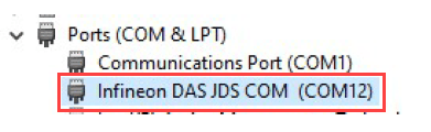
4. Select appropriate COM port for TC375x. To find the COM port number of the USB Serial Port showing in your host computer, browse to Device Manager > Ports (COM & LPT).
Verifying Top Model Code Using PIL
This example shows how to verify the generated code for a model by running a PIL simulation. With this approach:
You can verify code generated for a top model
You must configure the model to load test vectors or stimulus inputs from the MATLAB® workspace
You can easily switch the entire model between normal and PIL simulation mode
1. Open the tc3x_pil_top_model.slx model.

2. Choose the COM port.
3. Run the top model PIL simulation.
Open the Apps tab and select SIL/PIL Manager.
On the SIL/PIL tab, select SIL/PIL Mode > Processor-in-the-loop(PIL) option and click Run Verification.

4. When the PIL simulation is completed, a logsOut variable is created in the base workspace. The logsOut data contains PIL simulation results. You can access the logged data for signals count_a and count_b using the following commands:
count_a = get(logsOut,'count_a');
count_a.Values.Data
count_b = get(logsOut,'count_b');
count_b.Values.Data
Verifying Referenced Model Code Using PIL
This example shows how to verify the generated code for a referenced model by running a PIL simulation. With this approach:
You can verify code generated for referenced models
You must provide a test harness model to provide a test vector or stimulus inputs
You can easily switch a Model block between normal and PIL simulation mode
1. Open the tc3x_pil_model_block.slx model.
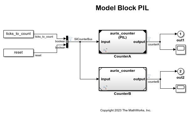
The model contains two Model blocks that both point at the same referenced model. Note, that the Hardware board change has to be made in the reference model also by double clicking on CounterTypeA or CounterTypeB to open the referenced model and following the steps above. You will configure one of the Model blocks to run in PIL simulation mode and the other in normal mode.
2. Choose the COM port.
3. Configure and run CounterA Model block in PIL simulation mode.
Right click on CounterA block and select Block Parameters (Model Reference)
Select Simulation mode > Processor-in-the-loop(PIL) and click OK

4. Run the Model Block PIL simulation.
Open the Apps tab and select SIL/PIL Manager
On the SIL/PIL tab, select System Under Test > Model blocks in SIL/PIL mode option and click Run Verification

5. When the model starts running, Scope1 displays the PIL simulation output running on the Infineon AURIX TC375 hardware board while Scope2 shows the normal mode simulation output.
Other Things to Try
Run the example on different Infineon AURIX TC3x Microcontrollers by changing the package class and pinout options and analyze the results.
Known Limitation
The tc3x_pil_model_block.slx model with DAS connectivity interface do not work with Simulink bus signals.