Design Top-Level Model
Create a top-level system-on-chip (SoC) application model using the reference models created in the previous steps.
Create and Configure Top-Level Model
Create a new blank model.
Configure the model for Infineon®AURIX™ hardware board.
In the Simulink editor, press Ctrl+E or click Modeling > Model Settings to open the Configuration Parameters dialog box.
Select the Hardware Implementation pane and set Hardware board to
Infineon AURIX TC3x.The Hardware board and the Device Series parameter values of the top-level model and the reference models must match.
Set the Processing Unit parameter to
Noneto indicate that the top-level model does not build.
Save the model.
Add Time-Based Reference Model
In the Simulink editor, add a Model block. Select the block and navigate to MODEL BLOCK > Block Parameters in the Simulink Toolstrip to open its Block Parameters dialog box.

Enable the Schedule rates parameter and set the Model name parameter value to one of the reference models created in the previous steps. For example, set the Model name to the time-based model
tc3x_ifx_tricore_0.slxby clicking the Browse button.
Add a Task Manager block and configure it for the TriCore® 0 reference model created in the Design Time-Based Simulink Model step.
Set the Type parameter to
Timer-drivenas the reference model uses time-based scheduling.Assign a name to the task with the Name parameter.
Set the Period to
0.5to match the Sample time value of the source blocks used in the reference model.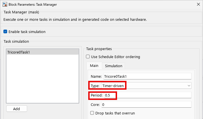
(Optional) On the Simulation tab, you can specify the task duration for that task. For more information on setting task duration, see Task Duration.
Note
To add different tasks in the same task manager block to handle tasks in reference models with subsystems running at multiple rates and with different scheduling requirements, click Add. For more information, see Modeling for Multitasking Execution and Rate Transitions and Asynchronous Blocks.
Connect the Task1 port to the input port of the Model block.

Add Event-Based Reference Model
Add another Model block and set the Model name parameter to a different reference model. For example, set the parameter to the event-based model
tc3x_ifx_tricore1.slxby clicking Browse.Add another Task Manager block and configure it for the TriCore 1 reference model created in Design Event-Based Simulink Model step.
Set the Type parameter to
Event-drivenas the reference model uses event-based scheduling.Assign a name to the task with the Name parameter.
Set the Priority to
50to match the priority value set in the Asynchronous Task Specification block used in the event-based reference model.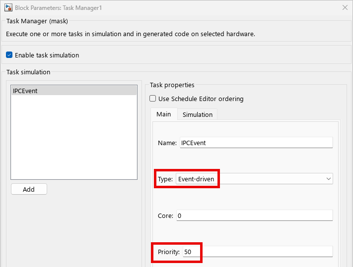
(Optional) On the Simulation tab, you specify the task duration for that task.
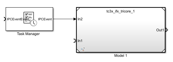
Adding the event-driven task exposes an event message input port on the Task Manager block. Connect the Task output port to the input port of TriCore 1 reference model.
Configure Communication Between Reference Models
Add an Interprocess Data Channel block to simulate communication from the TriCore 0 reference model to the TriCore 1 reference model.
Open the Block Parameters dialog box and select Show event port. This exposes an event output port on the Interprocess Data Channel block.

Connect the output event port of the Interprocess Data Channel block to the input event port of the Task Manager block.
Connect the data output port of the Interprocess Data Channel block to the data input port of the TriCore 1 reference model.
Connect the data output port of the TriCore 0 reference model to the data input port of the Interprocess Data Channel block.
Add another Interprocess Data Channel block to simulate communication from TriCore 1 reference model to TriCore 0 reference model.
Connect the data output port of the TriCore 1 reference model to the data input port of Interprocess Data Channel block.
Connect the data output port of the Interprocess Data Channel block to the data input port of TriCore 0 reference model.
The completed model is similar to this diagram.

To view and configure the peripheral blocks, the interrupts, and their parameters, on the Simulink toolstrip, on the Hardware tab, click Hardware Mapping. For more information, see Map Tasks and Peripherals Using Hardware Mapping.

After you complete the modelling, launch the SoC Builder tool to build and validate the model. To do so, in the Simulink® toolstrip, in the Hardware tab, click either Configure, Build, Deploy & Start, Configure & Build, or Configure, Monitor & Tune . SoC builder guides you through the steps to generate executables for the reference models, code, and program the hardware board. For more information, see Generate Code and Deploy Using SoC Builder.
See Also
Blocks
- Interprocess Data Read | Interprocess Data Write | Interprocess Data Channel | Task Manager | Model | Subsystem