Monolithic Modeling for Infineon AURIX Microcontrollers
Monolithic models are single-core based stand-alone models. Simulink® executes the generated code for monolithic models on any one of the processing units. You can design monolithic models that run in parallel but independently on one hardware platform, with each application having its own processing unit.
Embedded Coder® Support Package for Infineon® AURIX™ TC3x Microcontrollers supports time-based and event-based scheduling requirements. Time-based scheduling requirements apply to models that use a periodic interrupt source such as a hardware timer for timing. Event-based scheduling requirements apply to systems that must also support execution of blocks in response to events which are asynchronous with respect to the periodic timing source of the system.
Design Time-Based Monolithic Model
You can design models for algorithms that depend on time-based scheduling and for which you intend to generate code.
To create and configure a time-based monolithic model:
Create a new blank model.
Configure the model for Infineon AURIX hardware board.
In the Simulink editor, press Ctrl+E or click Modeling > Model Settings to open the Configuration Parameters dialog box.
Select the Hardware Implementation pane and set Hardware board to
Infineon AURIX
                           TC3x
. Set Processing Unit to the core you want to use for this model. For example, selectTriCore0.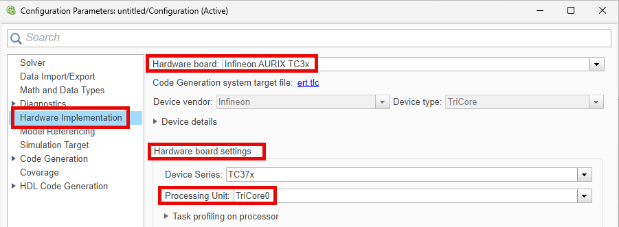
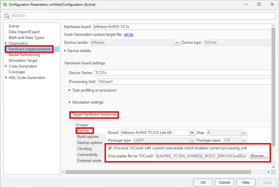
TriCore® 0 is the principal processing unit that handles system initialization, boot processes, and critical control tasks in the AURIX microcontrollers. If you design an application model to run on the processing units other than TriCore 0, then you must initialize these processing units by selecting Pre-load TriCore0 with custom executable which enables current processing unit in the Configuration Parameters dialog box.
You can provide your own custom executable file for the TriCore 0 processing unit by clicking Browse.
Save the model.
In the Simulink editor, add the blocks you need for your application. For example, consider these connections.

Provide sample time for the source block used in the model. For this example, in the Digital Port Read block, set the Sample time parameter to 0.5.
You can also group all the blocks into a subsystem and provide a sample time for the atomic subsystem. For more information, see Sample Time in Subsystems.
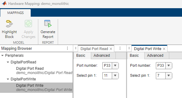
To view and configure the peripheral blocks and their parameters, on the Simulink toolstrip, on the Hardware tab, click Hardware Mapping. For more information, see Map Tasks and Peripherals Using Hardware Mapping.
Design Event-Based Monolithic Model
You can design models for algorithms that handle asynchronous events such as hardware-generated interrupts. These models support execution of blocks in response to events that are asynchronous with respect to the periodic timing source of the system. For example, a peripheral device might signal completion of an input operation by generating an interrupt. The system must service such interrupts, for example, by acquiring data from the interrupting device.
To create and configure an event-based Simulink model:
Create a new blank model.
Configure the model for Infineon AURIX hardware board.
In the Simulink editor, press Ctrl+E or click Modeling > Model Settings to open the Configuration Parameters dialog box.
Select the Hardware Implementation pane and set Hardware board to
Infineon AURIX
                           TC3x
. Set Processing Unit to the core you want to use for this model. For example, selectTriCore0.TriCore 0 is the principal processing unit that handles system initialization, boot processes, and critical control tasks in the AURIX microcontrollers. If you design an application model to run on the processing units other than TriCore 0, then you must initialize these processing units by selecting Pre-load TriCore0 with custom executable which enables current processing unit in the Configuration Parameters dialog box.
You can provide your own custom executable file for the TriCore 0 processing unit by clicking Browse.
Save the model.
Create an asynchronous task for the event based model.
In the Simulink editor, add a Hardware Interrupt block to the model. The task priority value must be set greater than 40 as the internal scheduling operates at a priority of 40. Set the Simulink Task priority parameter to
50.
You can also use a Function-Call Generator to generate software interrupts.
Add a Function-Call Subsystem block to the model. Connect the Default event output port of Hardware Interrupt block to the function() input port of the Function-Call Subsystem block.

Open the Function-Call subsystem and add the blocks you need for your application. For example, consider these connections.

To view and configure the peripheral blocks and their parameters, on the Simulink toolstrip, on the Hardware tab, click Hardware Mapping. For more information, see Map Tasks and Peripherals Using Hardware Mapping.

Multicore Modeling
You can design multicore application models with the time-based monolithic models, event-based monolithic models, or a combination of both. Use the Interprocess Data Read and Interprocess Data Write blocks to establish inter-core communication between the participating processing units.
In this workflow, you can generate software executables and code for the individual monolithic models and implement inter-core communication between the participating processing units. To simulate, deploy, verify, and validate the generated code, you must opt for the .
Follow these steps to create monolithic-based multicore models.
Create two monolithic models with unique processing units. These models can be both time-based, event-based or a combination of both. For more information on these modeling scenarios, refer to Design Time-Based Monolithic Model and Design Event-Based Monolithic Model.
Add an Interprocess Data Read block to each monolithic model. Configure the block parameters to support inter-core communication.
Disable the Enable simulation port parameter as Simulink does not support simulation of Interprocess Data Read block in this workflow.
Select Participating cores depending on the processing units you specified in the monolithic models.
For example, you can establish communication between the TriCore 0 and TriCore 1 based models by selecting the parameter value as
TriCore0<->TriCore1. This enables the Interprocess Data Read block to receive messages from the TriCore 1 processing unit.

Add an Interprocess Data Write block to each monolithic model. Configure the block parameters to support inter-core communication.
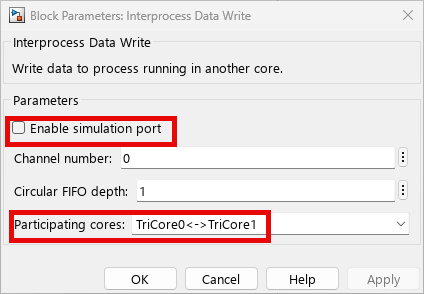
Disable the Enable simulation port parameter as Simulink does not support simulation of Interprocess Data Write block in this workflow.
Select Participating cores depending on the processing units you specified in the monolithic models.
For example, you can establish communication between the TriCore 0 and TriCore 1 based models by selecting the parameter value as
TriCore0<->TriCore1. This enables the Interprocess Data Write block to send messages to the TriCore 1 processing unit.
Known Limitations
PPU does not support time-based modeling.
Interrupts corresponding to Interprocess Data blocks are not supported for code generation.
Simulation of Interprocess Data Read and Interprocess Data Write blocks is not supported.
Simulation and code generation for Task Manager blocks is not supported.