Main Content

MIMO FIR Filter

Filter input signals through multipath MIMO FIR filter

Since R2025a

  • MIMO FIR Filter block

Libraries:
DSP System Toolbox / Filtering / Filter Implementations

Description

The MIMO FIR Filter block models a multiple-input multiple-output (MIMO) system which contains multiple FIR filters in the time domain. The block performs time-domain filtering, where the filtering operation involves a convolution between the input channel and the FIR filter on the specific path. You can specify the coefficients of multiple filters directly using the Numerator parameter or through the Num input port.

Using the Number of propagation paths parameter, you can specify the number of paths between each input and output channel pair. Each path contains a single time-domain FIR filter of the same length. The block adds the filtered outputs from each path. Additionally, depending on the setting of the Sum filtered output contributions from all input channels parameter, the block adds or concatenates these filtered output contributions. For more information, see Modeling MIMO System with Multiple Propagation Paths.

The number of channels in the output signal depends on the number of filters, number of paths between each input and output channel pair, and the number of input channels. For more details, see the y argument description.

The Frequency-Domain FIR Filter block also supports modeling MIMO and multipath systems. The block implements filtering in the frequency domain. Typically, time-domain filtering is efficient for smaller impulse responses and frequency domain filtering is efficient for longer impulse responses.

Examples

expand all

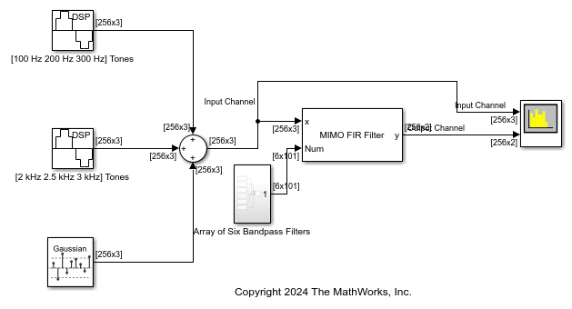
Filter an input signal using a 3-by-2 MIMO system with three input channels, two output channels, and one path between each input and output channel pair.

Open the filterSignalMIMOFIRBlock.slx model. Design six bandpass FIR filters with varying center frequencies. The bandwidth for each filter is 0.1.

Pass the filter coefficients you design through the Num port of the MIMO FIR Filter block. Select the Sum filtered output contributions from all input channels parameter.

The input contains two sinusoidal signals each with a frame length of 256. The first sinusoidal signal contains tones at 100 Hz, 200 Hz, and at 300 Hz. The second sinusoidal signal contains tones at 2 kHz, 2.5 kHz, and at 3 kHz. The input noise is white Gaussian with a mean of 0 and a variance of 0.01.

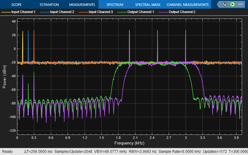
Run the model. Pass the signal through the designed MIMO FIR filter array. Since there are six filters, three input channels, and one path between each input and output channel pair, the number of output channels of the system is given by $6/(3*1) = 2$. Visualize the spectrum of the input and output signals in the spectrum analyzer.

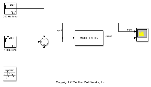
Filter an input signal through a single-input single-output system (SISO) that contains three distinct paths between the input and the output.

Open the multiPathMIMOFIRBlock.slx model. The input is a noisy sinusoidal signal with two tones, one at 200 Hz and the other at 4 kHz. The noise is a white Gaussian noise with a mean of 0 and a variance of 0.01. Pass this signal to the MIMO FIR Filter block.

Design three lowpass FIR filters with varying fractional delays, 0.1, 0.2, and 0.3. These filters model the frequency response across each path, respectively. The order of each filter is 400.

Here is the MATLAB® code to design the filter.

   order = 400;
   num = [designFracDelayFIR(0.1,order); % Path 1
          designFracDelayFIR(0.2,order); % Path 2
          designFracDelayFIR(0.3,order)]; % Path 3

In the MIMO FIR Filter block, set the Numerator parameter to num and Number of propagation paths to 3. The MIMO FIR Filter block now models a SISO system with three propagation paths between the input and the output.

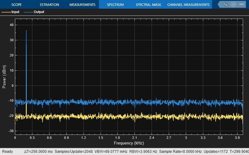
Run the model and visualize the spectrum of the input and the filtered output signals in the spectrum analyzer.

Ports

Input

expand all

Specify the data input as a vector or a matrix of size L-by-T. This block supports variable-size input signals, that is, you can change the input frame size (number of rows) during simulation. However, the number of channels (columns) must remain constant.

This port is unnamed until you set Numerator source to Input port.

Data Types: single | double
Complex Number Support: Yes

Specify the time-domain FIR filter coefficients as a row vector or a matrix input. For more information on the filter coefficients, see the Numerator parameter description.

If the numerator input is a row vector, the number of data input channels must be 1.

Dependencies

To enable this port, set Numerator source to Input port.

Data Types: single | double
Complex Number Support: Yes

Output

expand all

Filtered output, returned as a vector, matrix, or a 3-D array.

When the number of filters F is greater than 1 and you:

  • Select the Sum filtered output contributions from all input channels parameter, the block adds the filtered output from each input channel to generate an L-by-R output matrix, where L is the input frame size (number of input rows) and R is the number of output channels. R equals F/(T x P), where F is the number of filters, T is the number of input channels, and P is the value that you specify in the Number of propagation paths parameter.

  • Clear the Sum filtered output contributions from all input channels parameter, the block does not sum filtered output contributions from all input channels. The output is an L-by-R-by-T array. y(:,j,k) refers to the output from the kth input channel for the jth output channel. For example, y(:,3,2) indicates output on the third output channel from the second input channel.

For more information on how the block computes the output, see Modeling MIMO System with Multiple Propagation Paths.

The output has the same data type and complexity as the input signal.

Data Types: single | double
Complex Number Support: Yes

Parameters

expand all

To edit block parameters interactively, use the Property Inspector. From the Simulink® Toolstrip, on the Simulation tab, in the Prepare gallery, select Property Inspector.

Specify the source of the FIR filter coefficients as one of these:

  • Property –– Specify the filter coefficients through the Numerator parameter.

  • Input port –– Specify the filter coefficients through the Num input port.

Specify the time-domain FIR filter coefficients as a row vector (single filter) or a matrix (multiple filters) of size F-by-NumLen, where F is the number of filters and NumLen is the filter length. If F is greater than 1, then its value must be a multiple of the product of the number of input channels (columns) T and the number of paths P you specify through the NumPaths property. The multiplication factor determines the number of output channels R and equals F/(T × P).

The coefficient values can change during simulation but the size of the numerator must remain constant.

Tunable: Yes

Dependencies

To enable this parameter, set Numerator source to Property.

Data Types: single | double
Complex Number Support: Yes

Specify the number of propagation paths P between each input and output channel pair as a positive integer. Each path is represented by a unique filter. When you specify the number of paths to be greater than 1, the filter models multipath propagation. The block sums up filtered output contributions from all paths between each input and output channel pair.

For an example, see Filter Input Signal Through Multiple Propagation Paths.

Dependencies

To enable this parameter, the number of filters F must be greater than 1.

Data Types: single | double

Select this parameter to sum filtered output contributions from all input channels. The block adds the filtered output from each input channel to generate an L-by-R output matrix, where L is the input frame size (number of input rows) and R is the number of output channels. R equals F/(T x P), where F is the number of filters, T is the number of input channels, and P is the value that you specify in the Number of propagation paths parameter.

When you clear this parameter, the block does not sum filtered output contributions from all input channels. The output is an L-by-R-by-T array.

For more information on how the block computes the output based on the value of this parameter, see Modeling MIMO System with Multiple Propagation Paths.

Dependencies

To enable this parameter, the number of filters F must be greater than 1.

Data Types: Boolean

Clicking this button opens the filter visualizer and displays the magnitude response of the filters that you specify in the numerator matrix. The response is based on the parameters you select in the block dialog box. To update the magnitude response while the filter visualizer is running, modify the parameters in the dialog box and click Apply.

You can configure the plot settings and the signal measurements from the interface of the visualizer.

On the Scope tab of the filter visualizer toolstrip, the Configuration section allows you to modify the plot settings. On the Measurements tab, you can place data cursors and display the peak values of the selected signal.

For more details on the filter visualizer interface and its tools, see Configure Filter Visualizer.

Dependencies

To enable this button, set Numerator source to Property.

Specify the type of simulation to run. You can set this parameter to:

  • Interpreted execution –– Simulate model using the MATLAB® interpreter. This option shortens startup time.

  • Code generation –– Simulate model using generated C code. The first time you run a simulation, Simulink generates C code for the block. The C code is reused for subsequent simulations as long as the model does not change. This option requires additional startup time but provides faster subsequent simulations.

Block Characteristics

Data Types

double | single

Direct Feedthrough

no

Multidimensional Signals

no

Variable-Size Signals

yes

Zero-Crossing Detection

no

Algorithms

expand all

Extended Capabilities

expand all

C/C++ Code Generation
Generate C and C++ code using Simulink® Coder™.

Version History

Introduced in R2025a