Digilent Function Waveform Generator Channels
Waveform function generator channels on a Digilent® device can generate both standard and arbitrary function waveforms. For more
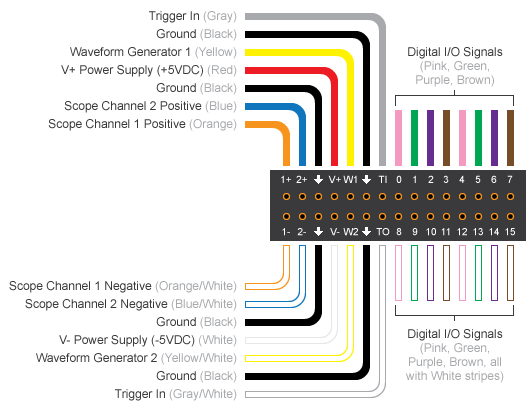
information, see Waveform Types. This diagram shows the pin
configuration on a typical Digilent
Analog Discovery device. The yellow and the yellow/white lines represent the waveform generator
channels, marked as W1 and W2 on the device.
To test the Analog Discovery device, create the following connection to acquire the generated waveform, and use it with the corresponding code:
1+(scope channel 1 positive) toWIthrough a1Kresistor.1–(scope channel 1 negative)W2toGND.
This diagram depicts these connections on a breadboard.

Unlike analog input channels, the waveform generator channels control their own frequency. If your DataAcquisition contains both waveform generator channels and any other type of acquisition channels, the waveform generator channels will have their own frequency and all other channels will inherit the DataAcquisition scan rate. If you have analog input channels in the DataAcquisition with waveform generator channels, the analog input channels start first and act as a trigger for the waveform generator channels.