Edit Compensator Dynamics in Control System Designer
Using Control System Designer, you can manually edit compensator dynamics to achieve your design goals. In particular, you can adjust the compensator gain, and you can add the following compensator dynamics:
Real and complex poles, including integrators
Real and complex zeros, including differentiators
Lead and lag networks
Notch filters
You can add dynamics and modify compensator parameters using the Compensator Editor or using the graphical Bode Editor, Root Locus Editor, or Nichols Editor plots.
This topic describes how to edit compensators using Control System Designer. For more information on editing compensators using a standalone open-loop editor, see Design Compensator Using Open-Loop Editor.
Compensator Editor
To open the Compensator Editor dialog box, in Control System Designer, in an editor plot area, right-click and select Edit Compensator. Alternatively, in the Data Browser, in the Controllers section, right-click the compensator you want to edit and click Open Selection.

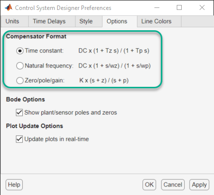
The Compensator Editor displays the transfer function for the currently selected compensator. You can select a different compensator to edit using the drop-down list. By default, the compensator transfer function displays in the time constant format. You can select a different format by changing the corresponding Control System Designer preference.
In Control System Designer, on the Control System tab, click Preferences. In the Control System Designer Preferences dialog box, on the Options tab, select a Compensator Format.

To add poles and zeros to your compensator, in the Compensator Editor, right-click in the Dynamics table and, under Add Pole or Zero, select the type of pole/zero you want to add.

The app adds a pole or zero of the selected type with default parameters.
To edit a pole or zero, in the Dynamics table, click on the pole/zero type you want to edit. Then, in the Edit Selected Dynamics section, in the text boxes, specify the pole and zero locations.
To delete poles and zeros, in the Dynamics table, click on the pole/zero type you want to delete. Then, right-click and select Delete Pole or Zero.
Graphical Compensator Editing
You can also add and adjust poles and zeros directly from Bode Editor, Root Locus Editor, or Nichols Editor plots. Use this method to roughly place poles and zeros in the correct area before fine-tuning their locations using the Compensator Editor.
To add poles and zeros directly from an editor plot, right-click the plot area
and, under Add Pole or Zero, select the type of pole/zero
system you want to add. In the editor plot, the app displays the editable
compensator poles and zeros as red X’s and O’s
respectively.
In the editor plots, you can drag poles and zeros to adjust their locations. As you drag a pole or zero, the app displays the new value in the status bar, on the right side.

To delete a pole or zero, right-click the plot area and select Delete Pole or Zero. Then, in the editor plot, click the pole or zero you want to delete.

Poles and Zeros
You can add the following poles and zeros to your compensator:
Real pole/zero — Specify the pole/zero location on the real axis
Complex poles/zeros — Specify complex conjugate pairs by:
Setting the real and imaginary parts directly.
Setting the natural frequency, ωn, and damping ratio, ξ.
Integrator — Add a pole at the origin to eliminate steady-state error for step inputs and DC inputs.
Differentiator — Add a zero at the origin.
Lead and Lag Networks
You can add lead networks, lag networks, and combination lead-lag networks to your compensator.
| Network Type | Description | Use This To |
|---|---|---|
| Lead | One pole and one zero on the negative real axis, with the zero having a lower natural frequency |
|
| Lag | One pole and one zero on the negative real axis, with the pole having a lower natural frequency |
|
| Lead-Lag | A combination of a lead network and a lag network | Combine the effects of lead and lag networks |
To add a lead-lag network, add separate lead and lag networks.
To configure a lead or lag network for your compensator, use one of the following options:
Specify the pole and zero locations. Placing the pole and zero further apart increases the amount of phase angle change.
Specify the maximum amount of phase angle change and the frequency at which this change occurs. The app automatically computes the pole and zero locations.
When graphically changing pole and zero locations for a lead or lag compensator, in the editor plot, you can drag the pole and zeros independently.
Notch Filters
If you know that your system has disturbances at a particular frequency, you can add a notch filter to attenuate the gain of the system at that frequency. The notch filter transfer function is:
where
ωn is the natural frequency of the notch.
The ratio ξ2/ξ1 sets the depth of the notch.
To configure a notch filter for your compensator, in the Compensator Editor dialog box, you can specify the:
Natural Frequency — Attenuated frequency
Notch Depth and Notch Width
Damping for the complex poles and zeros of the transfer function.
When graphically editing a notch filter, in the Bode Editor, you can drag the bottom of the notch to adjust ωn and the notch depth. To adjust the width of the notch without changing ωn or the notch depth, you can drag the edges of the notch.
