Design LQR Servo Controller in Simulink
This example shows the design of an LQR servo controller in Simulink® using an aircraft autopilot application.
Open the aircraft model.
open_system("lqrpilot")
In this model:
The
Linearized Dynamicsblock contains the linearized airframe.sf_aerodynis an S-Function block that contains the nonlinear equations for .The error signal between and the is passed through an integrator, which helps drive error to zero.
Opening the model also loads the lqrpilotData MAT file, which contains the following data.
State equation matrices
AandBLinearized state matrix
A15Final LQG gain matrix
K_lqr
Aircraft State-Space Equations
The equation is the standard state equation of a state-space system.
For the aircraft system, the state vector is as follows.
The variables , , and are the three velocities with respect to the body frame, as shown in the following figure.

The variables and are roll and pitch. , , and are the roll, pitch, and yaw rates, respectively.
The airframe dynamics are nonlinear. The following equation shows the nonlinear components added to the state space equation, where is the acceleration due to gravity.
Trimming
For LQG design purposes, the nonlinear dynamics are trimmed at and , , , and set to zero. Since , , and do not affect into the nonlinear term in the preceding equation, the result is a model linearized around with all remaining states set to zero.
The lqrdes script shows how to compute the linearized model A15 at this trimmed operating point.
Problem Definition
The goal for the design is to perform a steady coordinated turn, as shown in this figure.

To achieve this goal, you must design a controller that commands a steady turn by going through a 60° roll. In addition, assume that the pitch angle must stay as close to zero as possible.
Results
The lqrdes script shows how to calculate the LQG gain matrix K_lqr.
In the lqrpilot model, ensure that the switch block is configured to select the output of the Nonlinear Dynamics block.
Run the model.
sim("lqrpilot")View the response of the roll to a step-change of 60°. The system tracks the commanded roll within about 60 seconds.
open_system("lqrpilot/phi (roll angle)")

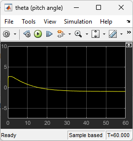
View the pitch angle . The controller was able to keep the pitch angle relatively small.
open_system("lqrpilot/theta (pitch angle)")
Finally, view the control inputs.
open_system("lqrpilot/Control Inputs")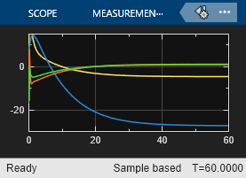

You can adjust the Q and R values in the lqrdes script to try different potential designs. Also, you can compare simulations of the linear and nonlinear system dynamics to see the effects of the nonlinearities on the system performance.