OSTBC Over 3-by-2 Rayleigh Fading Channel
Simulate orthogonal space-time block codes (OSTBC) to achieve diversity gains in a multiple-input multiple-output (MIMO) communications system. The example shows the transmission of data over three transmit antennas and two receive antennas using independent Rayleigh fading per link.
Explore Model
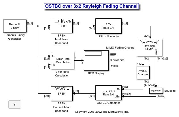
This figure shows the doc_ostc32 model. The model creates a random binary signal, modulates it using a binary phase shift keying (BPSK) technique, and then encodes the waveform using a rate 3/4 orthogonal space-time block code for transmission over the fading channel. The fading channel models six independent links that result from the three transmit by two receive antenna configuration of single-path Rayleigh fading processes. The simulation adds white Gaussian noise at the receiver, and then combines the signals from both receive antennas into a single stream for demodulation. For this combining process, the model assumes perfect knowledge of the channel gains at the receiver. The simulation compares the demodulated data with the original transmitted data and computes the bit error rate. The simulation runs until it processes 100 errors or 1e6 bits, whichever comes first.
Orthogonal Space-Time Block Code
This matrix shows the rate 3/4 code with three transmit antenna orthogonal space-time block code configured in the OSTBC Encoder block.

where  ,
,  , and
, and  correspond to the three symbol inputs for which the output is given by the previous matrix. The input to the OSTBC Encoder block is a 3-by-1 vector signal and the output is a 4-by-3 matrix. The number of columns in the output signal indicates the number of transmit antennas for this simulation, where the first dimension is for time. The OSTBC Combiner outputs a 3-by-1 vector.
For the rate 3/4 OSTBC code modeled, the output signal power per time step is 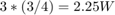 . A channel symbol carries 3 data bits, is 4 time steps long and has a period of 3e-3 seconds. At the receiver, there are two antennas resulting in
  bits per symbol per channel (antenna). In addition,
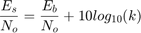
where k is the number of bits per symbol. Since the AWGN Channel block requires per channel values for input signal power and number of bits per symbol, set the Es/No value to EbNo+10*log10(3/2) to calibrate the white Gaussian noise added in the simulation.
Performance
Compare the performance of the model to theoretical results by using the Bit Error Rate Analysis app. This plot compares the simulated BER for a range of Eb/N0 values with the theoretical results for a diversity order of six.

The theoretical and simulated results align well. The variation between theoretical and simulated results is primarily due to the simulated fading channel model having a small Doppler fade. Since the simulated channel varies slightly over the block symbols, there is some variation between the simulated and theoretical results.
See Also
Blocks
You can also select a web site from the following list:
Americas
- América Latina (Español)
- Canada (English)
- United States (English)
Europe
- Belgium (English)
- Denmark (English)
- Deutschland (Deutsch)
- España (Español)
- Finland (English)
- France (Français)
- Ireland (English)
- Italia (Italiano)
- Luxembourg (English)
- Netherlands (English)
- Norway (English)
- Österreich (Deutsch)
- Portugal (English)
- Sweden (English)
- Switzerland
- United Kingdom (English)