Examine 256-QAM Using Simulink
This example shows you how to model a communications system with quadrature amplitude modulation (QAM), additive white Gaussian noise (AWGN) channel, and phase noise using Simulink®. The model displays constellation diagrams of the 256-QAM signal and performs bit error rate (BER) computations.
Overview
The cm_commphasenoise model, simulates the effect of AWGN and phase noise on a 256-QAM signal.

The Bernoulli Binary Generator block generates a random signal consisting of a sequence of 8-bit binary values in the range [0, 255].
The Rectangular QAM Modulator Baseband block modulates the signal using baseband 256-ary QAM.
The AWGN Channel block models a noisy channel by adding white Gaussian noise to the modulated signal.
The Phase Noise block introduces noise in the angle of its complex input signal.
The Rectangular QAM Demodulator Baseband block demodulates the signal.
These additional model blocks can help you interpret the simulation.
The Constellation Diagram block a displays constellation diagram of the signal with AWGN and phase noise added.
The Error Rate Calculation block counts bits that differ between the received signal and transmitted signal.
The To Workspace block, labeled
outputErr, outputs the results to the workspace for use when plotting the results.A Callback Button labeled
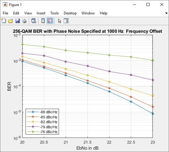
Display BER Plotopens a plot showing the Eb/N0 performance curves for 256-QAM transmission and reception at various levels of phase noise.
Digital Modulation
The model simulates QAM, which is a method for converting a digital signal to a complex signal. The model modulates the signal onto a sequence of complex numbers that lie on a lattice of points in the complex plane, known as the constellation of the signal. A plot of these points is called a scatterplot or constellation diagram of the signal.
The constellation diagram shown here displays the baseband 256-ary QAM with AWGN added, and with AWGN and phase noise added. The points in the constellation diagram do not lie exactly on the constellation shown in the figure because of the added noise. Phase noise alters the angle of the complex modulated signal, causing a radial displacement of constellation points.
Run the Simulation
The default model configuration has the run duration set to inf. The Error Rate Calculation block is configured to run until 100 errors occur. To stop the simulation before 100 errors occur, click Stop on the Simulation tab.
Display the Error Rate
The Display block displays the number of errors introduced by the AWGN channel and phase noise. When you run the simulation, three small boxes appear in the block, displaying the vector output from the Error Rate Calculation block. The vector values are [BER, total number of errors, total number of bits compared].
Display Phase Noise Plot
To display this plot figure of BER versus Eb/N0 curves over a range of phase noise settings, double-click the Display BER Plot block in the model.

Further Exploration
You can control the way a Simulink block functions by setting its parameters. To view or change simulation parameters, double-click a block to open its block mask.
To change the amount of phase noise, open the Phase Noise block mask and enter a new value for the Phase noise level (dBc/Hz) parameter. Click OK to apply the new setting.
To change the amount of noise, open the AWGN Channel block mask and enter a new value for the Eb/No (dB) parameter. Decreasing this parameter value increases the noise level. Click OK to apply the new setting.
Reducing the phase noise and increasing the Eb/N0 removes noise from the model. Since the model is configured to run until 100 errors occur, running the simulation with little noise in the model results in a long simulation run time. To limit the maximum simulation run time, you can reduce the run duration from inf to a small value, such as 10.
To produce new results, run the simulation using the modified settings.
Alternatively, you can enter a variable name in a parameter. Then at the MATLAB® command line set the value for that variable in the workspace. Setting parameters in the Command Window can be convenient when running multiple simulations with different parameter values.
You can also use callback functions to configure your simulation. The default setting for several parameters in this model are set using the PreLoadFcn callback function. For more information on model properties and callback functions, see Model Callbacks (Simulink).
Plot BER at Different Noise Levels
The plot_256qam_ber_curves.m MATLAB® program file generates the BER plot presented in this example by running multiple simulations with different values for the Phase noise level (dBc/Hz) and Eb/No (dB) parameters. Each curve is a plot of BER as a function of signal to noise ratio for a fixed amount of phase noise. For each plotted BER point, the simulation stopped when 1000 bit errors were reached or 1e8 bits were compared. Results vary from run to run due to the random nature of the input signal and simulation impairments.