Bluetooth Protocol Stack
The Bluetooth® Special Interest Group (SIG) [1] and [2] defines the protocol stack for Bluetooth low energy (LE) and Bluetooth basic rate/enhanced data rate (BR/EDR) technology. The fundamental objectives of these specifications are to develop interactive services and applications over interoperable radio components and data communication protocols.
This figure shows the architecture of the Bluetooth stack.
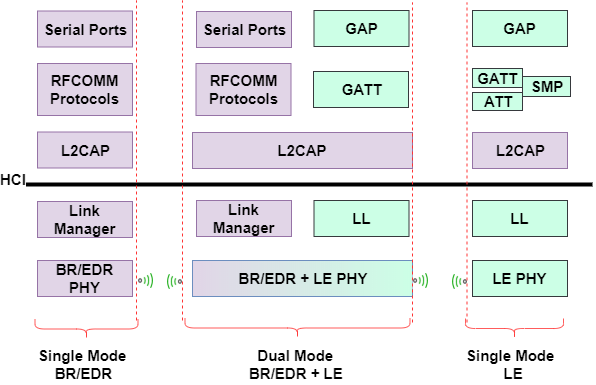
Bluetooth devices can be one of these two types:
Single mode – Supports a BR/EDR or LE profile
Dual mode – Supports BR/EDR and LE profiles
The subsequent sections provide details about the architecture of Bluetooth LE Protocol Stack and Bluetooth BR/EDR Protocol Stack.
Bluetooth LE Protocol Stack
This figure compares the Bluetooth LE protocol stack to the Open System Interconnection (OSI) reference model.
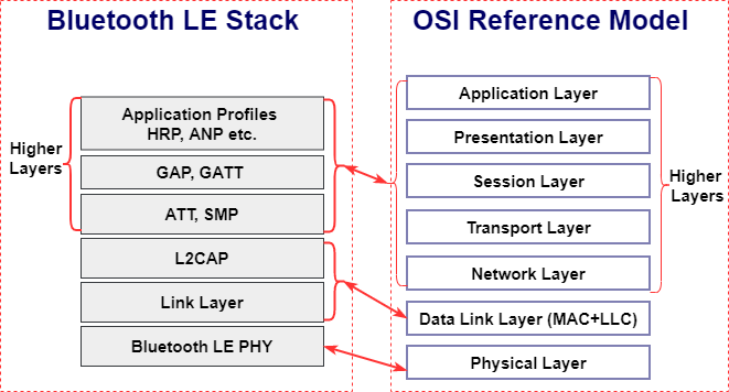
In the preceding figure, the Bluetooth LE protocol stack is shown along with the OSI reference model.
There is one-to-one mapping at the physical layer (PHY)
The OSI data link layer (DLL) maps to the Bluetooth LE logical link control and adaptation protocol (L2CAP) and link layer (LL)
In the Bluetooth LE stack, the higher layers provide application layer services, device roles and modes, connection management, and security protocol
The functionality of the Bluetooth LE protocol stack is divided between three main layers: the Controller, the Host, and Application Profiles and Services.

Controller
The controller layer includes the Bluetooth LE PHY, the LL, and the controller-side host controller interface (HCI).
Bluetooth LE PHY. The Bluetooth LE PHY air interface operates in the same unlicensed 2.4 GHz Industrial, Scientific, and Medical (ISM) frequency band as Wi-Fi®. The Bluetooth LE PHY air interface also includes these characteristics:
Operating radio frequency (RF) is in the range 2.4000 GHz to 2.4835 GHz, inclusive.
The channel bandwidth is 2 MHz. The operating band is divided into 40 channels, k = 0, …, 39. The center frequency of the kth channel is 2402 + k × 2 MHz.
User data packets are transmitted using channels in the range [0, 36].
Advertising data packets are transmitted in channels 37, 38, and 39.
Gaussian frequency shift-keying (GFSK) modulation scheme is implemented.
The Bluetooth LE PHY uses frequency-hopping spread spectrum (FHSS) to reduce interference and to counter the impact of fading channels. The time between frequency hops can vary from 7.5 ms to 4 s and is set at the connection time for each Peripheral.
Support for throughput at 1 Mbps is mandatory for specification version 4.x compliant devices. At a data rate of 1 Mbps, the transmission is uncoded.
Optionally, devices compliant with the Bluetooth Core Specification version 5.1 support these additional data rates:
Coded transmission at bit rates of 500 kbps or 125 kbps
Uncoded transmission at a bit rate of 2 Mbps
LL. The LL performs tasks similar to the medium access control (MAC) layer of the OSI model. In Bluetooth, the LL interfaces directly with the Bluetooth LE PHY and manages the link state of the radio to define the role of a device as Central, Peripheral, Advertiser, or Scanner.
Controller-Side HCI. The HCI on the controller side handles the interface between the host and the controller. The HCI defines a set of commands and events for transmission and reception of packet data. When receiving packets from the controller, the HCI extracts raw data at the controller to send to the host.
Host
The host includes the host-side HCI, L2CAP, attribute protocol (ATT), generic attribute profile (GATT), security manager protocol (SMP), and generic access profile (GAP).
Host-Side HCI. The HCI on the host side handles the interface between the host and the controller. The HCI defines a set of commands and events for transmission and reception of packet data. When transmitting data, the HCI translates raw data into packets to send them from the host to the controller.
L2CAP. The L2CAP encapsulates data from the Bluetooth LE higher layers into the standard Bluetooth LE packet format for transmission or extracts data from the standard Bluetooth LE LL packet on reception according to the link configuration specified at the ATT and SMP layers.
ATT. The ATT transfers attribute data between clients and servers in GATT-based profiles. The ATT defines the roles of the client-server architecture. The roles typically correspond to the Central and the Peripheral as defined in the link layer. In general, a device could be a client, a server, or both, irrespective of whether it is a Central or a Peripheral. The ATT also performs data organization into attributes as shown in this figure.
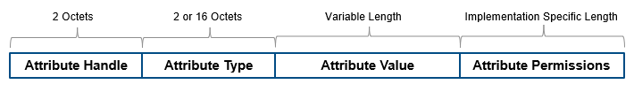
Device attributes are represented as:
The attribute handle is a 16-bit identifier value assigned by the server to enable a client to reference those attributes.
The attribute type is a universally unique identifier (UUID) defined by Bluetooth SIG. For example, UUID 0x2A37 represents a heart-rate measurement.
The attribute value is a variable length field. The UUID associated with and the service class of the service record containing the attribute value, determine the length of the attribute value field.
Attribute permissions are sets of permission values associated with each attribute. These permissions specify read and write privileges for an attribute, and the security level required for read and write permission.
GATT. The GATT provides a reference framework for all GATT-based profiles. The GATT encapsulates the ATT and is responsible for coordinating the exchange of profiles in a Bluetooth LE link. Profiles include information and data such as handle assignment, a UUID, and a set of permissions.
For devices that implement the GATT profile,
The client is the device that initiates commands and requests toward the server. The client can receive responses, indications, and notifications.
The server is the device that accepts incoming commands and requests from the client. The server sends responses, indications, and notifications to the client.
The GATT uses client-server architecture. The roles are not fixed and are determined when a device initiates a defined procedure. Roles are released when the procedure ends.
The terminology used in the GATT includes:
Service — A collection of data and associated behaviors used to accomplish a particular function or feature
Characteristic — A value used in a service along with appropriate permissions
Characteristic descriptor — A description of the associated characteristic behavior
GATT-Client — A GATT-Client initiates commands and requests towards the server and can receive responses, indications, and notifications sent by the server
GATT-Server — A GATT-Server accepts incoming commands and requests from a client and sends responses, indications, and notifications to the client
SMP. The SMP applies security algorithms to encrypt and decrypt data packets. This layer defines the initiator and the responder, corresponding to the Central and the Peripheral, once the connection is established.
GAP. The GAP specifies roles, modes, and procedures of a device. It also manages the connection establishment and security. The GAP interfaces directly with the Application Profiles and Services (App) layer.
APP Layer
The App layer is the direct user interface defining profiles that afford interoperability between various applications. The Bluetooth core specification enables vendors to define proprietary profiles for use cases not defined by SIG profiles.
Note
For more information about the Bluetooth LE protocol stack architecture, see Volume 3, Part C, Sections 2 and 2.1 of the Bluetooth Core Specification [1].
Bluetooth BR/EDR Protocol Stack
This figure compares the block diagram of the Bluetooth BR/EDR protocol stack and with the OSI reference model.
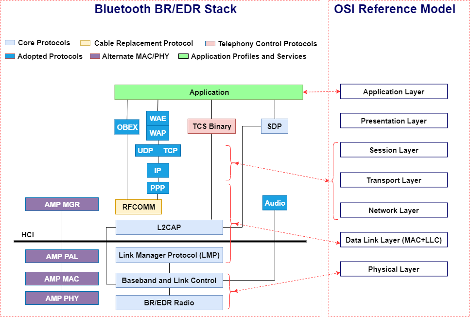
The mapping of BR/EDR stack to the OSI reference model is as shown below:
The BR/EDR Radio and Baseband and Link Control layers of the Bluetooth BR/EDR stack map to the OSI PHY layer.
The Link Manager Protocol (LMP), L2CAP, Cable Replacement Protocol (RFCOMM), and PPP layers of the Bluetooth BR/EDR stack map to the OSI data link layer.
The user datagram protocol (UDP), transmission control protocol (TCP), and internet protocol (IP) layers of Bluetooth BR/EDR stack map to a combined, network, transport and session layers of the OSI reference model.
There is one-to-one mapping at the application layer.
Core Protocols
The Bluetooth core protocols and the Bluetooth radio are required by most of the Bluetooth devices. The core protocols include these layers.
BR/EDR Radio. The BR/EDR radio is the lowest defined layer of the Bluetooth specification. The BR mode is mandatory, whereas the EDR mode is optional. This layer defines the requirements of the Bluetooth transceiver device operating in the 2.4 GHz ISM frequency band. It implements a 1600 hops/sec FHSS technique. The radio hops in a pseudo-random way on 79 designated Bluetooth channels. Each Bluetooth channel has a bandwidth of 1 MHz. Each frequency is located at (2402 + k) MHz, where k = 0,1,...78. The modulation technique for BR and EDR mode is GFSK and differential phase shift keying (DPSK), respectively. The baud rate is 1 Msymbols/s. The Bluetooth BR/EDR radio uses the time division duplex (TDD) topology in which data transmission occurs in one direction at one time. The transmission alternates in two directions, one after the other.
Baseband and Link Control. The baseband and link control layer enables the PHY RF link between different Bluetooth devices, forming a piconet. The baseband handles the channel processing and timing, and the link control handles the channel access control. This layer provides these two different types of PHY RF links with their corresponding baseband packets:
Synchronous connection-oriented (SCO) – Supports real-time audio traffic
Asynchronous connection-oriented (ACL) – Supports data packet transmission
Link Manager Protocol (LMP). The LMP layer is primarily responsible for link setup and link configuration between different Bluetooth devices. These processes include establishing security functions such as authentication and encryption by generating, exchanging, and checking link and encryption keys. Furthermore, this layer controls the power modes and duty cycles of the Bluetooth radio device and the connection states of a Bluetooth unit in a piconet.
L2CAP. The L2CAP adapts higher-layer protocols over the baseband. It shields the higher-layer protocols from the details of the lower-layer protocols. The L2CAP provides connection-oriented and connectionless services to the higher-layer protocols. This includes protocol multiplexing capability, segmentation and reassembly operations, and group abstractions.
SDP. Discovery services are an important aspect of the Bluetooth framework. The service discovery protocol (SDP) provides a means for applications to query services and the characteristics of services, following which a connection can be established between two or more Bluetooth devices. The SDP is quite different from service discovery in traditional network-based environments. The SDP is built on top of the L2CAP.
Cable Replacement Protocol
The cable replacement protocol in the Bluetooth BR/EDR stack uses RFCOMM to provide emulation of serial ports over L2CAP. RFCOMM emulates RS-232 control and data signals over the Bluetooth baseband and provides transport capabilities for higher-layer services that use a serial interface as a transport mechanism. RFCOMM also provides multiple simultaneous connections to one device and enables connections to multiple devices.
Telephony Control Protocols
The telephony control protocol specification, binary (TCS binary), defines the call control signaling to establish data and voice calls between Bluetooth devices. It is built on top of the L2CAP. Moreover, TCS binary defines mobility management procedures for handling Bluetooth devices.
Adopted Protocols
In addition to the core protocols, the Bluetooth BR/EDR stack includes protocols adopted from other standard bodies. These adopted protocols are defined in specifications issued by other standard-making organizations and are incorporated into the Bluetooth framework.
PPP. The point-to-point protocol (PPP) is an Internet Engineering Task Force (IETF) [3] standard protocol for transporting IP datagrams over a point-to-point link. The PPP runs over the RFCOMM to realize point-to-point connections.
TCP, UDP, and IP. These layers are the IETF-defined foundation protocols of the TCP/IP protocol suite.
TCP – This protocol provides a reliable virtual connection between devices to realize data communication. The TCP treats the data as a stream of bytes and transmits them without any errors or duplication.
UDP – This protocol is an alternative to the TCP and provides an unreliable datagram connection between devices. As there is no end-to-end connection in UDP, data is transmitted link-by-link without any guarantee of service.
IP – This layer is a network layer protocol that enables a datagram service between devices, supporting both the TCP and UDP.
The use of the TCP, UDP, and IP in the Bluetooth BR/EDR stack enables communication with any other device connected to the Internet.
OBEX. The object exchange (OBEX) protocol is a session-level protocol developed by the Infrared Data Association (IrDA) to exchange objects. The OBEX protocol provides functionality similar to that of HTTP, but in a simpler manner. HTTP is an application layer protocol and layered above the TCP/IP. The OBEX protocol provides the client with a reliable transport for connecting to a server. It also provides a model for representing objects and operations.
WAE and WAP. Bluetooth BR/EDR stack incorporates the wireless application environment (WAE) and wireless application protocol (WAP) into its architecture. The advantages of using WAE/WAP features in the Bluetooth stack are:
Build application gateways that act as an interface between WAP servers and some other application on the PC
Provide functions such as remote control and data fetching from the PC to the Bluetooth handset
Reuse the upper software application developed for the WAP application environment
Application Profiles and Services
For more information, see APP Layer.
Alternate MAC/PHY
The alternate MAC/PHY (AMP) manager is a secondary controller in the Bluetooth core system. After an L2CAP connection is established between two devices over the BR/EDR radio, the AMP manager can discover the AMPs that are available on the other device. If an AMP is common between two devices, the Bluetooth core system provides mechanisms for moving data traffic from the BR/EDR controller to an AMP controller.
Each AMP manager consists of a protocol adaptation layer (PAL) on top of a MAC and PHY. The PAL maps the Bluetooth protocols to the specific protocols of the underlying MAC and PHY.
L2CAP channels can be created on, or moved to, an AMP. If an AMP physical link has a link supervision timeout, then L2CAP channels can be moved back to BR/EDR radio. To minimize power consumption in the device, AMPs are enabled or disabled as required.
HCI
The HCI provides a command interface to the BR/EDR radio, baseband controller, and the link manager. It is a single standard interface for accessing the Bluetooth baseband capabilities, the hardware status, and the control registers.
Note
For more information about the Bluetooth BR/EDR protocol stack architecture, see Volume 1, Part A, Sections 2 and 2.1 of the Bluetooth Core Specification [1].
References
[1] Bluetooth Special Interest Group (SIG). "Bluetooth Core Specification." v6.1. https://www.bluetooth.com/specifications/specs/core-specification-6-1/.
[2] Bluetooth Technology Website. “Bluetooth Technology Website | The Official Website of Bluetooth Technology.” Accessed November 6, 2021. https://www.bluetooth.com/.
[3] IETF. “Internet Standards.” Accessed November 6, 2021. https://www.ietf.org/.
[4] Bluetooth Protocol Stack - an Overview | ScienceDirect Topics. Accessed November 15, 2021. https://www.sciencedirect.com/.