Author AUTOSAR Compositions and Components in Architecture Model
Develop AUTOSAR compositions and components for the Classic Platform using an architecture model.
An AUTOSAR architecture model provides resources and a canvas for developing AUTOSAR composition and component models. From the architecture model, you can:
Add and connect AUTOSAR compositions and components.
Create architecture views for analysis.
Link components to requirements (requires Requirements Toolbox).
Define component behavior by creating, importing, or linking Simulink models.
Define and share interfaces, data types, and constants using Simulink data dictionaries.
Configure scheduling and simulation.
Export composition and component ARXML descriptions and generate component code (requires Embedded Coder).
Architecture models provide an end-to-end AUTOSAR software design workflow. In Simulink, you can author a high-level application design, implement behavior for application components, add Basic Software (BSW) service calls and implementations, and simulate the application.
Create Architecture Model
To begin developing AUTOSAR compositions and components in a software architecture canvas, create an AUTOSAR architecture model (requires System Composer).
1. Open the Simulink Start Page by either entering the MATLAB command simulink, or by selecting the Simulink button ![]() from the Simulink section of the toolstrip.
from the Simulink section of the toolstrip.
2. On the New tab, scroll down to AUTOSAR Blockset and expand the list of model templates. Place your cursor over the Software Architecture template and click Create Model.
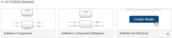
A new AUTOSAR architecture model opens.
3. Explore the controls and content in the software architecture canvas.
In the Simulink Toolstrip, the Modeling tab supports common tasks for architecture modeling.
To the left of the model window, the palette includes icons for adding different types of AUTOSAR components to the model. For classic architectures, supported component blocks include Classic Component, Software Composition, and for Basic Software (BSW) modeling, Diagnostic Service Component and NVRAM Service Component.
The composition editor provides a view of AUTOSAR software architecture based on the AUTOSAR Virtual Function Bus (VFB). The model canvas initially is empty.
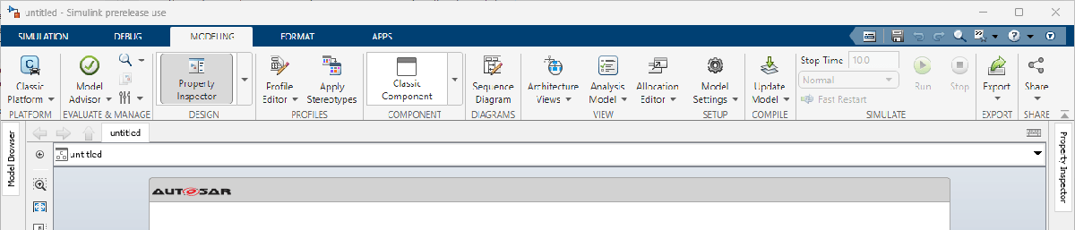
You select the architecture platform, Classic Platform or Adaptive Platform, from the Modeling tab. The default is classic. Mixing classic and adaptive components in the same architecture model is not supported.
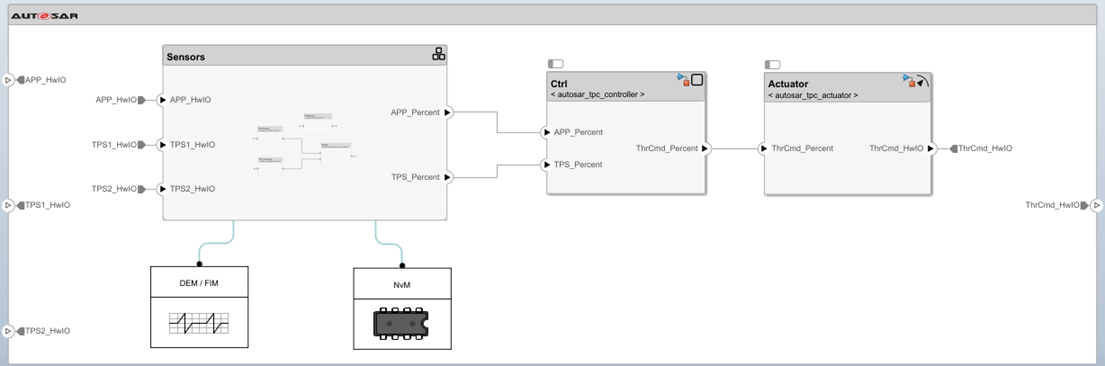
This example constructs a throttle position control application. Perform the steps in a new classic architecture model or refer to example model autosar_tpc_composition, which shows the end result.
open_system('autosar_tpc_composition')Add Compositions and Components and Link Implementation Models
The behavior of the AUTOSAR application is defined by its AUTOSAR components, which you link to Simulink implementation models. This example provides a Simulink implementation model for the AUTOSAR components of the following models:
autosar_tpc_throttle_sensor1.slxfor componentTPS_Primaryautosar_tpc_throttle_sensor2.slxfor componentTPS_Secondaryautosar_tpc_throttle_sensor_monitor.slxfor componentMonitorautosar_tpc_pedal_sensor.slxfor componentPedalSensorautosar_tpc_controller.slxfor componentCtrlautosar_tpc_actuator.slxfor componentActuator
Four of the above throttle position control components are sensor components. These sensor components can be combined to create a Software Composition block, Sensors. In your architecture model, you can create this Sensors composition in two ways. You can start by creating a blank composition and populate it with the relevant components or you can create the composition from the components.
Use Components to Create Composition
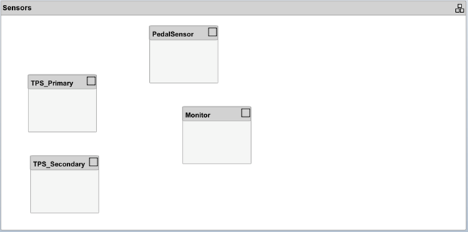
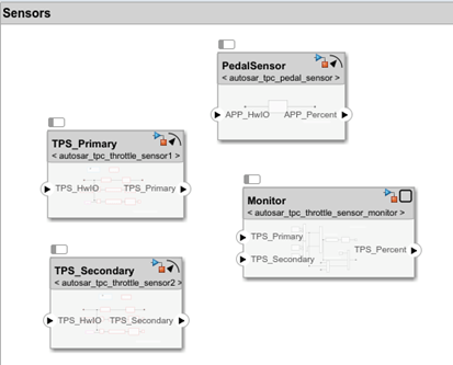
1. On the Modeling tab, select Classic Component to add Classic Component blocks to represent AUTOSAR components of the above models: TPS_Primary, TPS_Secondary, Monitor, and PedalSensor.
2. Select the four components. Either click and drag a rectangle, or select multiple components by holding the Shift key down. Pause over the ellipses, and select the Create Composition from Selection option.
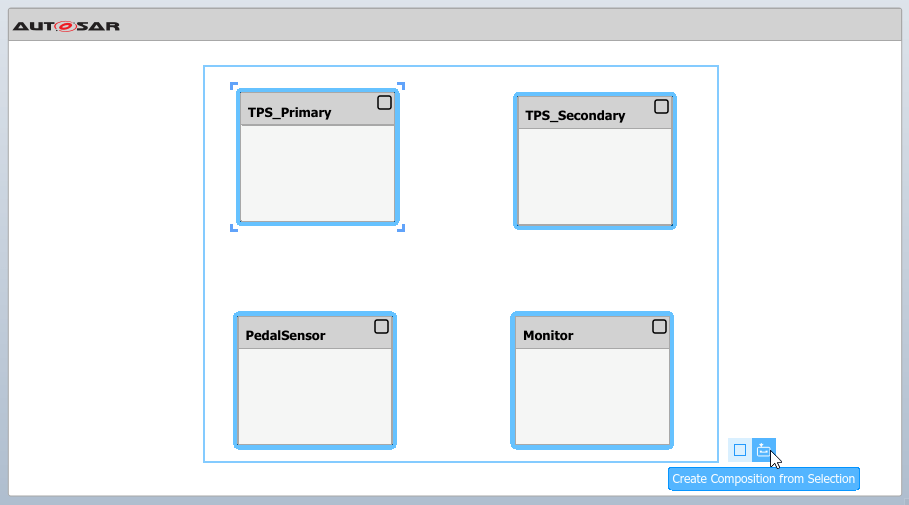
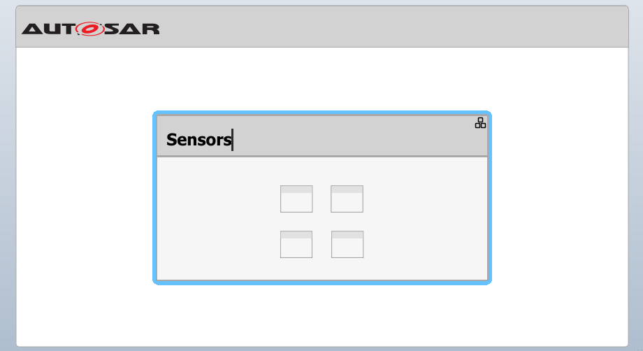
3. As a result the created composition block contains the selected components. Name the created Software Composition block, Sensors.
Create Composition and Add Components
1. Add a Software Composition block to the canvas. On the Modeling tab, select Software Composition adding a Software Composition block to the canvas. In the highlighted name field, write Sensors.
2. Open the Sensors composition to expose its contents on the canvas. On the Modeling tab, select Classic Component to add Classic Component blocks to represent AUTOSAR components of the above models: TPS_Primary, TPS_Secondary, Monitor, and PedalSensor.
Link Components to Simulink Models
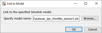
1. Link each component to a Simulink model that implements its behavior. Open the Sensors composition block if not already open and select the TPS_Primary component block, place your cursor over the displayed ellipsis, and select the cue Link to Model.
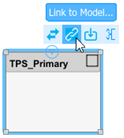
In the Link to Model dialog box, browse to the implementation model autosar_tpc_throttle_sensor1.slx. Click OK. Repeat for all four components, but instead linking to the corresponding Simulink model.
In an architecture model, when you link a component block to an implementation model, the software verifies whether the specified model meets linking requirements. Some requirements are that the implementation model must use the same target as the architecture model, use a fixed-step solver, and use root-level bus ports. If the implementation model does not meet one or more of these linking requirements, the software opens the AUTOSAR Model Linker app, which offers fixes for the unmet requirements. For more information, see Link to Implementation Model.
The implementation models provided for this example meet the linking requirements.
2. After you link each model, you can resize the associated component block to better display the component ports.
3. Connect the components to each other and to composition root ports.
To interconnect components, drag a line from a component provider port to another component receiver port.
To connect components to the
Sensorscomposition root ports, drag from a line from a component port to theSensorscomposition boundary.
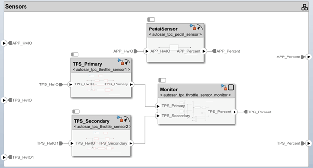
Optionally, to exactly match the root port naming in example model autosar_tpc_composition, rename ports TPS_HwIO and TPS_HwIO1 to TPS1_HwIO and TPS2_HwIO.
4. Return to the top level of the architecture model. To complete the application, add two Classic Component blocks and name them Ctrl and Actuator. Link these AUTOSAR components to their Simulink implementation models, autosar_tpc_controller.slx and autosar_tpc_actuator.slx. Connect the Sensors composition, Ctrl component, and Actuator component to each other and to the architecture model boundary.
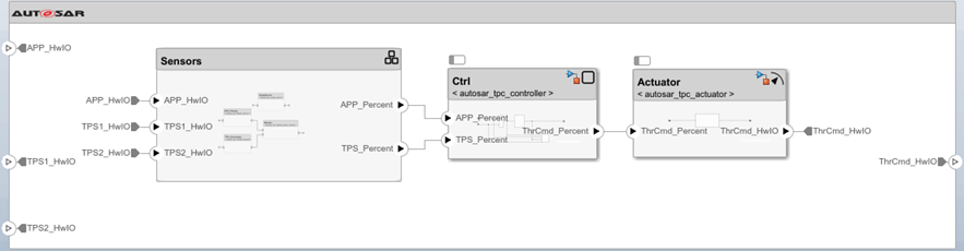
5. To check for interface or data type issues, update the architecture model. On the Modeling tab, select Update Model. If issues are found, compare your model with example model autosar_tpc_composition.slx.
6. Save the model with a unique name.
Create AUTOSAR Architectures from Compositions
If you have a composition saved in an AUTOSAR architecture model and would like to reference it from a different architecture model you can save the composition as a Simulink implementation model and reference it.
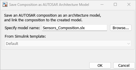
1. Place your cursor over the displayed ellipsis of the Sensors composition and select the option Save Composition as Architecture Model.

2. In the Save Composition as AUTOSAR Architecture Model dialog box, specify the name of the implementation model as Sensors_Composition.slx.
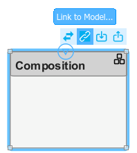
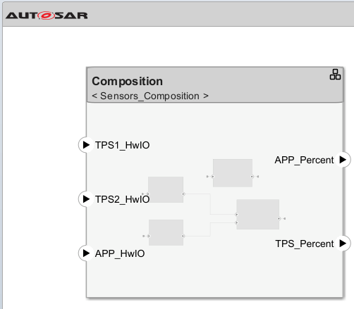
3. Create a new AUTOSAR architecture model, and add a composition block to the canvas.
4. Hover your cursor over the ellipsis above the Composition block.
5. Select Link to Model.
6. In the Link to Model dialog select Browse... and navigate to and select the 'Sensors_Composition.slx' file.
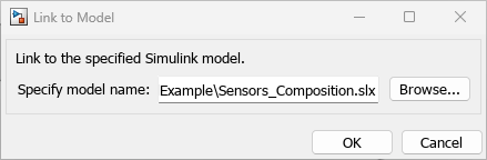
7. Click OK.
Optional: Use Data Dictionaries to Manage Interfaces, Data Types, and Constants
The Architectural Data section of a Simulink data dictionary allows you to create and configure interfaces, data types, and constants and then use them across multiple models. The models in this example use the shared data dictionary tpc_interfaces.sldd. The Architectural Data Editor can be used to graphically edit the interfaces across these models. For information regarding how to manage data dictionaries using the Architectural Data Editor, see Manage AUTOSAR Architectural Data With Data Dictionaries.
Open the Architectural Data Editor by either entering the command archdataeditor in the MATLAB Command Window or by selecting the Architectural Data Editor ![]() from the Modeling toolstrip of the architecture model. Open or create a data dictionary from the Architectural Data Editor. In this example, open the existing dictionary
from the Modeling toolstrip of the architecture model. Open or create a data dictionary from the Architectural Data Editor. In this example, open the existing dictionary tpc_interfaces.sldd.
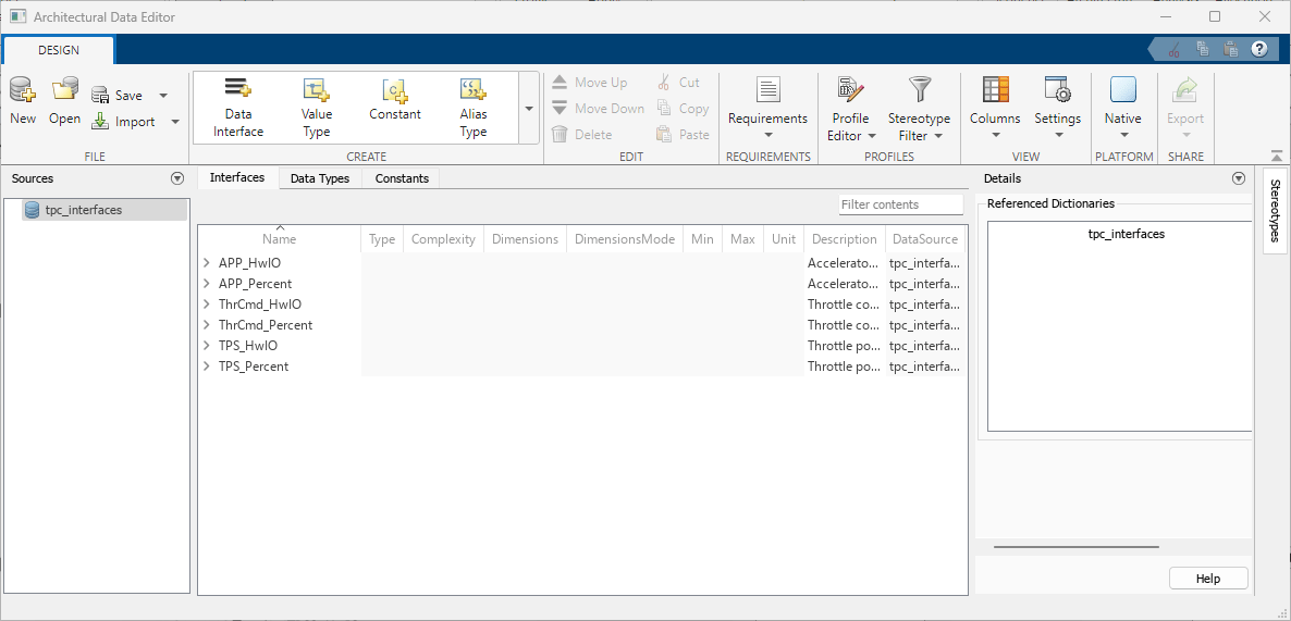
Data dictionary tpc_interfaces is used as the data source for the interfaces present in the architecture model. You can add, delete, and modify interfaces, data types and constants from their respective tabs.
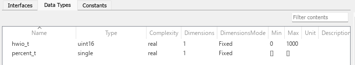
You can configure interfaces using the data types defined in the Architectural Data Editor. Many of the interfaces in tpc_interfaces are defined using custom data types. You can also define interfaces using built-in data types.
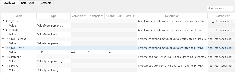
Interfaces APP_Percent, APP_HwIO, ThrCmd_Percent, TPS_Percent, and TPS_HwIO are configured using Simulink.ValueType objects that are defined on the Data Types tab.
To have your changes appear in the model, save the data dictionary and update the architecture model.
Optional: Create Architecture Views for Analysis
To help analyze structural and functional aspects of an AUTOSAR architecture model, you can create a filtered view of the model hierarchy. On the Modeling tab, in the Architecture Views menu:
Select Spotlight to create a spotlight view.
Select Architecture Views to create a custom view with grouping criteria.
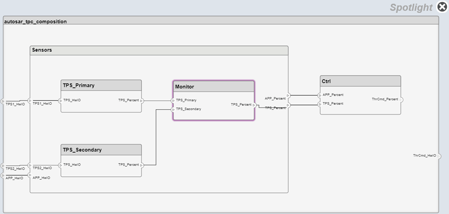
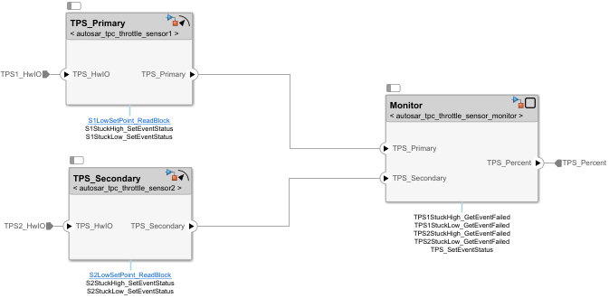
To help analyze component or composition dependencies, create a spotlight view. A spotlight view is a simplified view of an architecture component or composition that captures its upstream and downstream dependencies.
For this example, select the component Monitor, either in the example model autosar_tpc_composition or in the architecture model that you created and saved. On the Modeling tab, select Architecture Views > Spotlight.
The spotlight view opens and shows the model elements to which the component or composition connects in a hierarchy. The spotlight diagram is laid out automatically and cannot be edited.
Optionally, you can create spotlight views in separate, persistent model windows. Updating the architecture model diagram with changes refreshes open spotlight views. While in spotlight view, you can move the spotlight focus.
To create a custom view with more sophisticated filtering conditions, use the Architecture Views Gallery. On the Modeling tab, select Architecture Views. Custom views can be saved with the architecture model, then accessed and shared by collaborating users. For more information, see Create Profiles Stereotypes and Views for AUTOSAR Architecture Analysis.
Optional: Link Components to Requirements (Requirements Toolbox)
If you have Requirements Toolbox software, you can link components in the architecture model to requirements. The example folder provides sample requirements file TPC_Requirements.slreqx. The file contains requirements for four of the throttle position control application components.
To link a component to a requirement:
1. Open the Requirements Manager app. In the architecture model window, the Requirements tab opens, with the Requirements Browser docked at the bottom.
2. In the Requirements Browser, open requirements set TPC_Requirements.slreqx. The requirements set contains requirements for four components in the model.
3. To link an AUTOSAR component to a requirement, drag the requirement from the Requirements Browser to the component block. For example, drag requirement 4 to the Actuator component block.
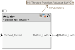
For more information, see Link AUTOSAR Components to Requirements.
Configure and Run Simulation
To simulate the behavior of the aggregated components in an AUTOSAR architecture model, click Run.
If you try to run the classic architecture model constructed in this example, an error message reports that a function definition was not found for a Basic Software (BSW) function caller block. Three of the component implementation models contain BSW function calls that require BSW service implementations.
To view those function calls, open your architecture model, for example, myTPC_Composition.slx. On the Debug tab, under Information Overlays, click Connectors. Select Function Connectors from the Connectors pane on the Simulink canvas. This selection lists function connectors for each model with functions. To see the models with BSW function calls, open the Sensors composition.
The models contain function calls to Diagnostic Event Manager (Dem) and NVRAM Manager (NvM) services. Before the application can be simulated, you must add Diagnostic Service Component and NVRAM Service Component blocks to the top model.
To add and configure the service implementation blocks:
1. Return to the top level of the architecture model and select the Modeling tab. Select and place an instance of Diagnostic Service Component and an instance of NVRAM Service Component. To wire the function callers to the BSW service implementations, update the model.
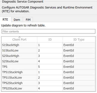
2. Check the mapping of the BSW function-caller client ports to BSW service IDs. Dem client ports map to Dem service event IDs and NvM client ports map to NvM service block IDs.
For this example, update the Dem mapping. Open the DEM/FIM block dialog box, select the RTE tab, and enter the event ID values shown. Click OK. For more information about BSW ID mapping, see Simulate AUTOSAR Basic Software Services and Run-Time Environment.
The architecture model is now ready to be simulated. Click Run.
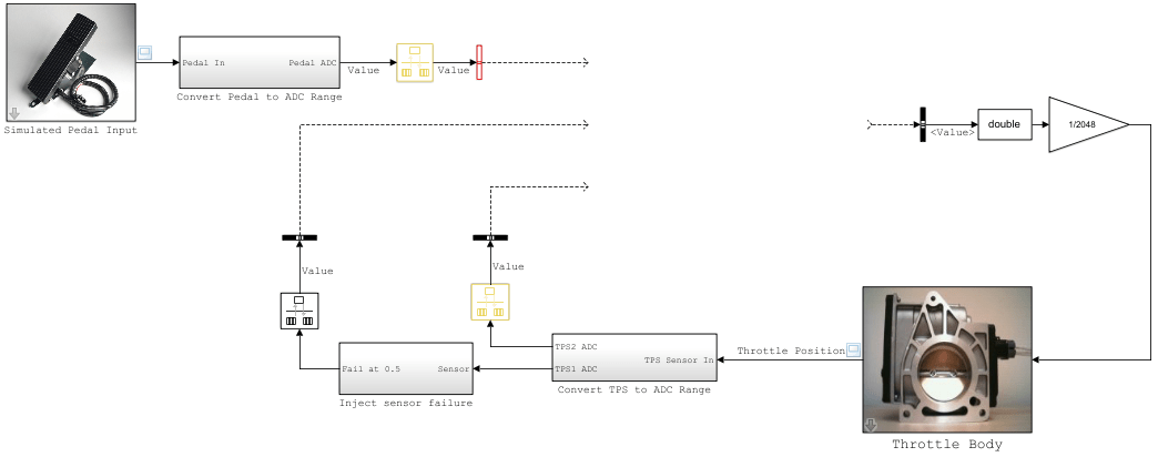
Connect Architecture Model to Test Harness Containing Plant Model and Pedal Input
To provide simulated pedal input to the throttle position control simulation, you can place the architecture model in a test harness model. The test harness can provide a plant model with a pedal input block. Refer to example test-harness model autosar_tpc_system.slx.
To connect the architecture model to the test harness:
1. Insert a Model block.
2. Configure the Model block to reference your architecture model, for example, myTPC_Composition.slx.
3. In the Model block dialog box, select the option Schedule rates. For the associated parameter Schedule rates with, select Schedule Editor. The throttle position control components have explicit partitions that you can schedule with the Schedule Editor.
4. Connect the architecture model ports to the test harness signals.
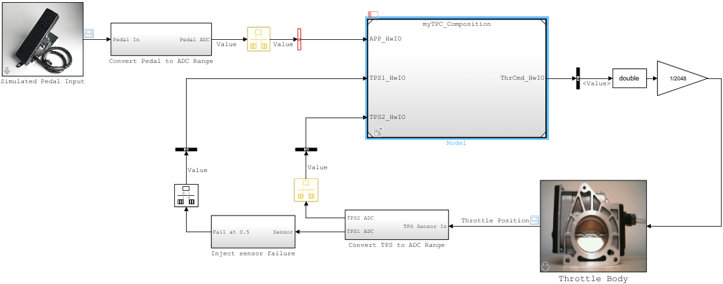
The test harness model is now ready to be simulated. Click Run. When you simulate the application, the throttle position scope indicates how well the throttle-position control algorithms in the architecture model are tracking the accelerator pedal input.
In a test harness model, from the Model block for a referenced AUTOSAR architecture model, you can use the Schedule Editor to schedule rates for component runnables. To open the Schedule Editor, click the Schedule Editor badge immediately above the Model block. In the Schedule Editor display, you can visualize and control the order of execution of the runnables (partitions) in the application components. For more information, see Using the Schedule Editor, Configure AUTOSAR Runnable Execution Order, and Configure AUTOSAR Scheduling and Simulation.
Export and Package Composition ARXML Descriptions and Component Code (Embedded Coder)
If you have Simulink Coder and Embedded Coder software, you can export composition and component AUTOSAR XML (ARXML) descriptions and generate component code from an AUTOSAR architecture model. Optionally, create a ZIP file to package build artifacts for the model hierarchy, for example, for relocation and integration.
To export ARXML files and generate code:
1. Open the architecture model constructed in this example or open example model autosar_tpc_composition.slx.
2. To prepare for exporting ARXML, examine and modify XML options. On the Modeling tab, select XML Options. The AUTOSAR Dictionary opens in the XML Options view. XML options specified at the architecture model level are inherited during export by each component in the model.
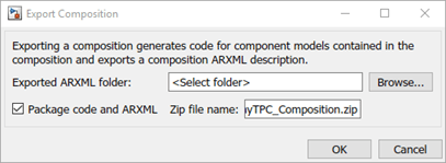
3. To generate and package code for the throttle position control application, on the Modeling tab, select Share > Generate Code and ARXML. In the Export Composition dialog box, specify the name of the ZIP file in which to package the generated files. To begin the export, click OK.
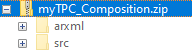
As the architecture model builds, you can view the build log in the Diagnostic Viewer. First the component models build, each as a standalone top-model build. Finally, composition ARXML is exported. When the build is complete, the current folder contains build folders for the architecture model and each component model in the hierarchy, and the specified ZIP file.
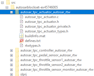
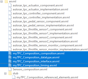
4. Expand the ZIP file. Its content is organized in arxml and src folders.
5. Examine the arxml folder. In this example, because XML Option Exported XML File Packaging is set to Modular, XML is exported into multiple files, named according to the type of information contained. Each AUTOSAR component has component and implementation description files, while the architecture model has composition, datatype, interface, and timing description files. The composition file includes XML descriptions of the composition, component prototypes, and composition ports and connectors. The datatype, interface, and timing files aggregate elements from the entire architecture model hierarchy. Nonfunctional properties captured in stereotypes and profiles are not included in the description files.
6. Examine the src folder. Each component model has a build folder that contains artifacts from a standalone model build.