Configure and Simulate AUTOSAR Classic Models with Simulink Real-Time
By using Simulink® Real-Time™ and Speedgoat I/O Blockset, you can simulate and fine-tune your AUTOSAR Classic component models using rapid control prototyping and hardware-in-the-loop testing.
This workflow requires a Simulink Test™ license to create a test harness.
To learn more about system requirements for deploying a Simulink Real-Time model onto a Speedgoat® target computer, see Product Requirements & Platform Availability for Simulink Real-Time.
Generate Simulink Real-Time Test Harness and Model from AUTOSAR Component Models for Rapid-Prototyping and Simulation
This example shows how to open, convert, and update an AUTOSAR model using the Simulink Real-Time environment.
Open the example model
autosar_swc_expfcns.openExample("autosar_swc_expfcns");Validate and simulate the model.
Open the AUTOSAR Component Designer app. On the AUTOSAR tab click Share and then select Generate Simulink Real-Time Model and Test Harness.
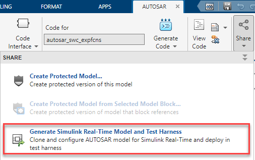
In the Export AUTOSAR Model for Simulink Real-Time Testing dialog box, in the Simulink Real-Time model folder box, specify the full file path of an output folder to store the Simulink Real-Time generated files and test harness model. This output folder must be empty before generating Simulink Real-Time files.
Simulink closes all open models and creates a Simulink Real-Time model
autosar_swc_expfcns_slrt, and a test harnessautosar_swc_expfcns_harness, which referencesautosar_swc_expfcns_slrt.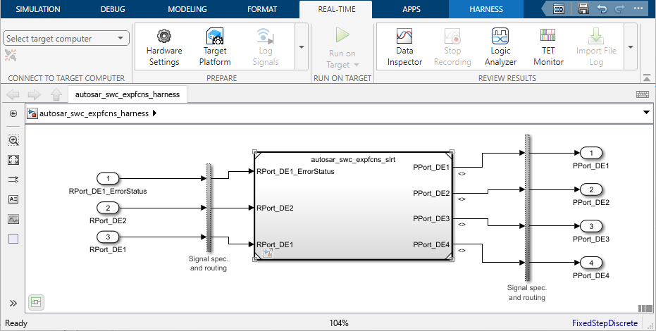
Set Up Speedgoat Target Computer and Configure Simulink Real-Time
This example shows how to connect to a target computer using Simulink Real-Time Explorer (Simulink Real-Time).
In the Simulink Editor, open the Simulink Real-Time Explorer. In the Real-Time tab, from the targets list, click SLRT Explorer.
From the Target Computers list, select the target computer node.
To add a node representing another target computer, in the Targets pane, click Add target.
To remove a node representing a target computer, select the node and click Remove target.
If the target computer has not been previously configured, select the Target Configuration tab and set the target computer IP address for the target computer definition by clicking Change IP Address button. Enter the IP address of the target computer. For example, Speedgoat target machines are preconfigured to address
192.168.7.5.Note
The target network setting values are for demonstration purposes only. Consult your network administrator for actual values. For more information about network configuration, see Target Computer Settings (Simulink Real-Time).
Start the target computer and wait until the target computer boots the real-time operating system (RTOS).
Update the target computer by clicking Update Software in the Target Configuration tab.
To connect Simulink Real-Time to the target computer, in the toolstrip, click the Disconnected button to toggle it to Connected.
Log Signals and Tune Parameters
This example shows how to create a Simulink Real-Time test harness and model for the
example model autosar_swc_counter, and then tune parameters while
seeing real-time updates by using Simulink
Real-Time Explorer (Simulink Real-Time) and the Simulation Data
Inspector (Simulink Real-Time).
Connect to your Speedgoat target computer by following the steps in the previous section.
Open the
autosar_swc_countermodel.model = "autosar_swc_counter"; openExample(model);To tune parameters in referenced models, open the Configuration Parameters dialog box and navigate to Model Referencing > Options for referencing this model. Set the Total number of instances allowed per top model parameter to
One.Alternatively, enter the below command in the MATLAB command window.
set_param(model,ModelReferenceNumInstancesAllowed='Single');Click Apply and then click OK.
In the model, select the
sum_outsignal. Log the signal by pausing over the action bar that appears and selecting Log Selected Signal.Open the Configuration Parameters dialog box and navigate to Code Generation > Optimization. Set Default parameter behavior as
Tunableand clock OK and save the model.Prepare the model for Simulink Real-Time by using the
autosar.slrealtime.migrateModelfunction, whereoutputFolderis an empty folder on the MATLAB path. If the folder does not exist then, Simulink creates it.autosar.slrealtime.migrateModel(model,"outputFolder", ... HarnessModelName="myAUTOSAR_SLRT_harness", ... OpenFlag = true)Once the migration completes,
myAUTOSAR_SLRT_harnessopens.Check that the System target file is
speedgoat.tlc. If System target file isslrealtime.tlc, install Speedgoat I/O Blockset and change System target file tospeedgoat.tlc.On the Real-Time tab, select your target computer from the menu in the Connect to Target Computer section.
To open the Target Platform Selector, in the Prepare section of the toolstrip, click Target Platform.
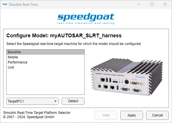
In the Target Platform Selector, select your target computer from the drop-down list and then select the appropriate configuration. This example uses the
Baselineconfiguration.On the Real-Time tab of the
myAUTOSAR_SLRT_harnessmodel, click Run on Target and then select Build application.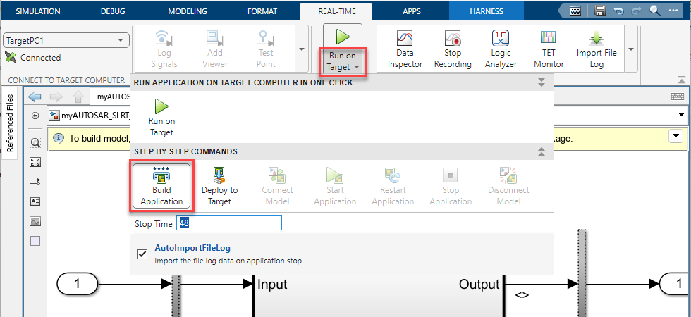
Open Simulink Real-Time Explorer. In the Prepare section of the toolstrip, click Load application and then select the generated
myAUTOSAR_SLRT_harness.mldatxfile.Navigate to the Parameters tab where you can see parameters
INC,LIMIT, andRESET.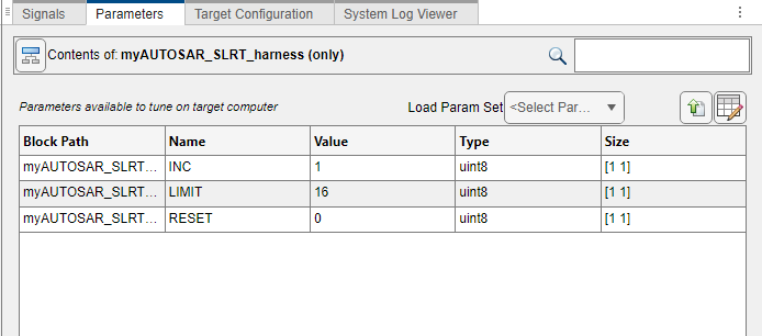
Open the Simulation Data Inspector (Simulink Real-Time). In Simulink Real-Time Explorer click Start
 .
.In the Simulation Data Inspector the signal
sum_outappears, check the box to begin plotting the signal.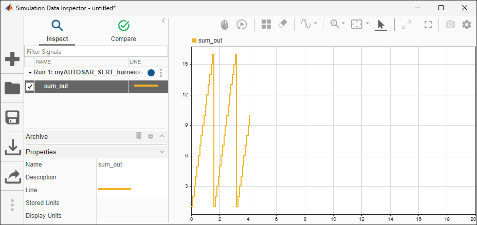
While the application is running, change the
LIMITparameter from16to22and see the data change in the Simulink Data Inspector in real time.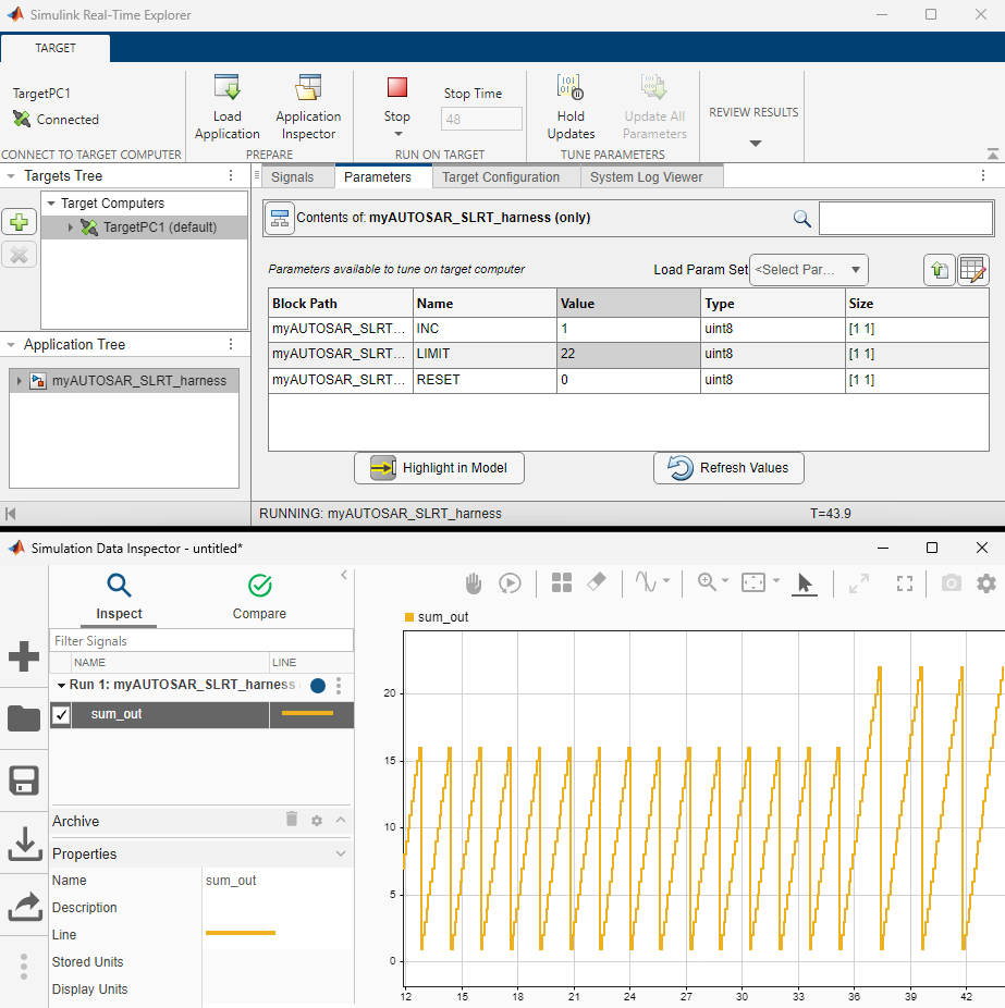
In order for this change to appear in the original AUTOSAR model you will need to open
autosar_swc_counterand change the value of theLIMITparameter to22.
See Also
Apps
- AUTOSAR Component Designer | Simulink Real-Time (Simulink Real-Time) | Simulink Real-Time Explorer (Simulink Real-Time) | Simulation Data Inspector (Simulink Real-Time)