Design and Analyze Curved Reflector Antennas
This example shows how to design and analyze the curved reflector antennas. Curved reflector antennas are an upgraded version of rectangular reflector antennas. The curved reflector surface of these antennas reflects and focuses the signal, thereby increasing the signal strength. Some of the notable characteristics of the curved reflectors are high gain, low cross-polarization, and reasonable bandwidth.
This example shows the design and analysis of cylindrical and spherical type curved reflector antennas. The later half of the example shows the comparison between the radiation patterns of these curved reflectors and other types of backing structures.
Design and Analyze Cylindrical Reflector Antenna
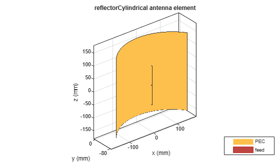
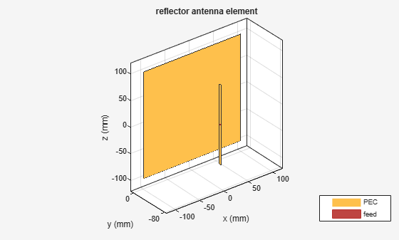
Cylindrical reflector antenna uses a cylindrical surface as a reflector. This reflector coexists with an antenna in various wireless transmission applications such as radar, general satellite communications, and radio astronomy. The function of the reflector is to focus a beam of signal towards a specific direction for an enhanced antenna gain. Use the reflectorCylindrical object and its following properties to define the cylindrical reflector and an exciter system.
GroundPlaneLength— Length of the ground plane in metersGroundPlaneWidth— Width of the ground plane in metersDepth— Perpendicular distance from origin to cylindrical reflector aperture in meters
GL = 0.3;
GW = 0.3;
D = 0.075;
cref = reflectorCylindrical(GroundPlaneLength=GL, GroundPlaneWidth=GW, Depth=D);
cref.Tilt = 90;
cref.Exciter.TiltAxis = [1 0 0];
cref.Exciter.Tilt = 90;
show(cref)
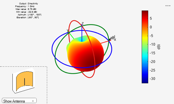
Plot the radiation pattern of the cylindrical reflector at 1 GHz.
pattern(cref,1e9)
view(-26,39)
Design and Analyze Spherical Reflector Antenna
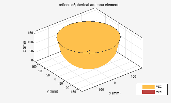
Create a spherical reflector antenna by taking a cross section from the sphere and suitable for wide-angle scanning. The spherical reflector can provide beam scanning from a fixed reflecting surface without any distortion. This reduces scanning system cost in compared to a conventional reflector antenna systems. The cost reduction comes in eliminating the need to move the primary reflecting surface at all elevation angles. Use the reflectorSpherical objects and its following properties to define a spherical reflector and an exciter system.
Radius— Radius of the aperture in metersDepth— Perpendicular distance between origin and the aperture of the antenna in meters
R = 0.15;
D = 0.15;
sref = reflectorSpherical(Radius=R, Depth=D);
show(sref)
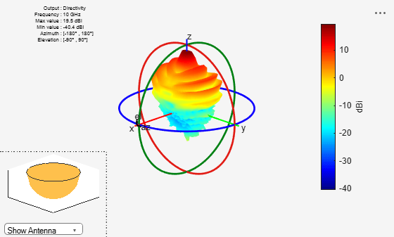
Plot the radiation pattern of the spherical reflector backed dipole at 10 GHz.
pattern(sref,10e9)
Azimuth Radiation Pattern of Rectangular and Cylindrical Reflector Antennas
Plot the azimuth patterns of rectangular and cylindrical reflector antennas to compare their radiation characteristics.
Create the rectangular reflector antenna object.
antR = reflector;
antR.Tilt = 90;
antR.Exciter.TiltAxis = [1 0 0];
antR.Exciter.Tilt = 90;
show(antR)
Plot the azimuth pattern plots for the rectangular and the cylindrical reflector antennas and compare their results.
pa1 = patternAzimuth(antR,1e9,0,"Azimuth",0:-1:-360);
pa2 = patternAzimuth(cref,1e9,0,"Azimuth",0:-1:-360);
figure
polarpattern(pa1);
hold on;
polarpattern(pa2);
hold off;
l = legend("Rectangular Reflector","Cylindrical Reflector");
l.Position = [0.6 0.8877 0.2996 0.0869];
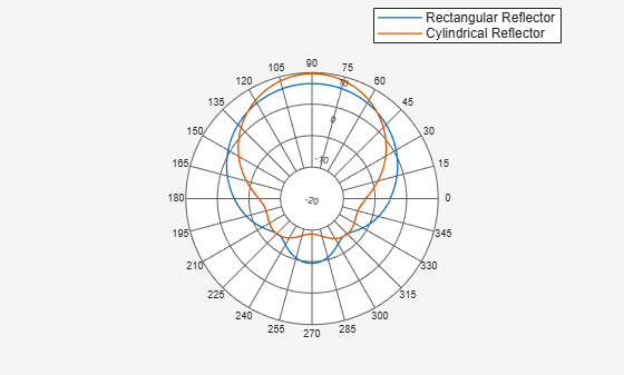
Cylindrical reflectors, on account of their curvature, provide higher gain compared to the rectangular reflectors.
Elevation Plots of Spherical and Parabolic Reflectors
Plot the elevation patterns of spherical and parabolic reflector antennas to compare their radiation characteristics.
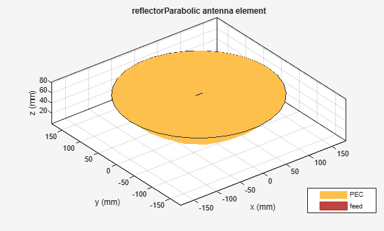
Create a parabolic reflector antenna.
pref = reflectorParabolic;
show(pref)
Compare the elevation pattern plots of the parabolic and the spherical reflector antennas.
pe1 = patternElevation(pref,10e9,0,Elevation=0:360);
pe2 = patternElevation(sref,10e9,0,Elevation=0:360);
figure
polarpattern(pe1)
hold on;
polarpattern(pe2)
l = legend("Parabolic Reflector","Spherical Reflector");
l.Position = [0.6 0.8877 0.2996 0.0869];
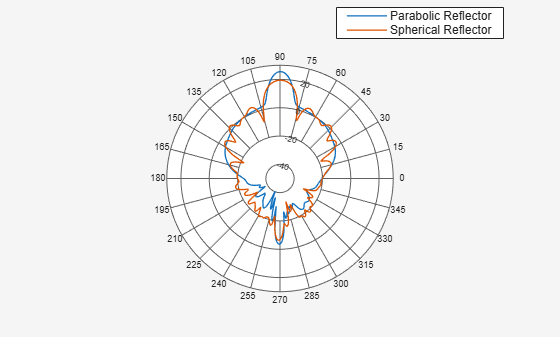
The elevation pattern plot of the spherical reflector shows more peaks as compared to the parabolic reflector meaning a spherical reflector scans a wider area.
Reference
[1] Balanis, Constantine A. Antenna Theory: Analysis and Design. 3rd ed. Hoboken, NJ: John Wiley, 2005.
[2] Zali H.M., M.T.Ali, I.Pasya, N.A.Halili , H.Ja’afar, M.Hilmi. ''Design of a Cylindrical Parabolic Reflector on Monopole Plasma Antenna''. IEEE International RF and Microwave Conference (RFM), Penang, 2013, pp. 344-348.