Quadcopter Control and Sensors
You must create a control system and set sensors for the quadcopter.
Control System
To create a control system for a Parrot quadcopter minidrone, you must design algorithms and controllers that manage the stability, altitude, orientation, and trajectory of the drone.
When designing the control system for a minidrone, consider the specific dynamics and constraints of the drone, as well as the requirements of the intended mission or application. Safety, stability, and responsiveness are critical aspects of the control system design.
For control, the quadcopter uses a complementary filter to estimate attitude, and Kalman filters to estimate position and velocity.
The model implements the controller and estimators as subsystems, which allows you to evaluate several combinations of estimators and controllers for design.
Quadcopter Flight Control System
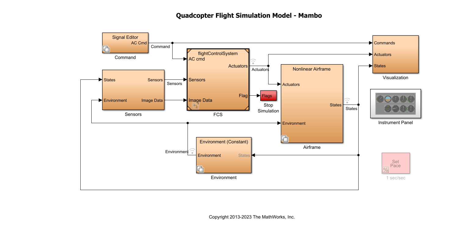
Inputs. The inputs of the flight control system (FCS) are:
Aircraft command — From
CommandsubsystemSensors — From the
SensorssubsystemImage data — From the
Sensorssubsystem
Components. The main components of the FCS are:
Image Processing system — The system uses the image data from the sensors and computes the landing flag, which forms the input to the landing logic control system. The subsystem detects whether dominance of red is detected in the image from the camera.
Landing Logic — The landing logic system initiates the controller to land the quadcopter based on the landing flag, which is set based on the camera data, and the landing Override flag, which is set if the vehicle closes in on the safe limit of 0.6 m (height from the ground).
Estimators — The subsystem uses the sensor subsystem outputs to estimate the states of the vehicle using a complementary filter (for attitude) and Kalman filters (for position and velocity).
Controller — The implemented controller logic uses:
A PID controller for yaw.
A cascaded PID controller for X-Y position.
A cascaded PID controller for pitch/roll orientation.
A PID controller for altitude.
Crash predictor flag — The flag is set based on the vehicle state values. The simulation is stopped based on the optical flow velocity (u or v is >0 .01).
The controllerVars file contains variables pertinent to the
controller. The estimatorVars file contains variables
pertinent to the estimator. The values are based on these files https://github.com/Parrot-Developers/RollingSpiderEdu/tree/master/MIT_MatlabToolbox/trunk/matlab/libs/RoboticsToolbox.
Sensors
You can use either of these types of sensors in the model:
Feedthrough sensors
Dynamic sensors
The Sensor Subsystem block in the quadcopter example takes the
vehicle's states and environment values as input and outputs simulated sensor
measurements, including IMU and optical flow data. It provides acceleration, angular
rate, and optical flow outputs for use in state estimation and control. The optical flow
data is computed using a crude implementation using the states as input.
In the feedthrough variant, sensor outputs like acceleration and angular rates are generated directly from the states with added bias. In the dynamic variant, the Three-axis Inertial Measurement Unit block simulates the physical sensor dynamics for acceleration and angular rates.
This workflow uses a set of sensors to determine the states of the quadcopter. These states describe the orientation and position of the quadcopter:
VNED — Velocity in earth reference frame
XNED — Position in earth reference frame
Euler — Euler rotation angles φ, θ, and ψ
DCMbe — Coordinate transformation from Earth axes to body-fixed axes
Vb — Velocity in the body-fixed frame
ɷb — Angular rates in body-fixed axes
dɷb/dt — Angular accelerations
Abe — Accelerations with respect to inertial frame
The system stores the characteristics for the sensors in sensorVars. To
include sensor dynamics with these measurements, you can change the
VSS_SENSORS variable in the workspace. VSS_SENSORS =
0 corresponds to the Feedthrough sensors and VSS_SENSORS =
1 corresponds to Dynamic sensors.