Ideal Airspeed Correction
Introduction
This case study simulates indicated and true airspeed. It constitutes a fragment of a complete aerodynamics problem, including only measurement and calibration.
Airspeed Correction Models
To view the airspeed correction models, enter the following at the MATLAB® command line:
openExample('aeroblk_indicated')
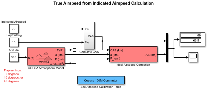
aeroblk_calibrated
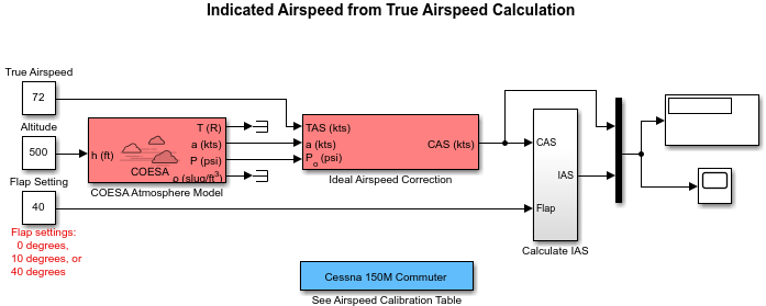
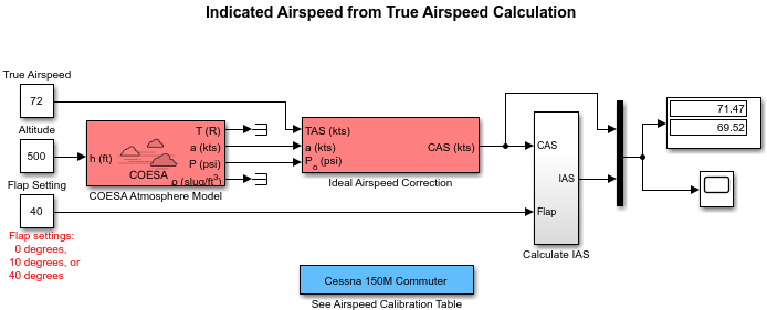
aeroblk_indicated Model
aeroblk_calibrated Model

Measure Airspeed
To measure airspeed, most light aircraft designs implement pitot-static airspeed indicators based on Bernoulli's principle. Pitot-static airspeed indicators measure airspeed by an expandable capsule that expands and contracts with increasing and decreasing dynamic pressure. This is known as calibrated airspeed (CAS). It is what a pilot sees in the cockpit of an aircraft.
To compensate for measurement errors, it helps to distinguish three types of airspeed. These types are explained more completely in the following.
Airspeed Type | Description |
|---|---|
Calibrated | Indicated airspeed corrected for calibration error |
Equivalent | Calibrated airspeed corrected for compressibility error |
True | Equivalent airspeed corrected for density error |
Calibration Error
An airspeed sensor features a static vent to maintain its internal pressure equal to atmospheric pressure. Position and placement of the static vent with respect to the angle of attack and velocity of the aircraft determines the pressure inside the airspeed sensor and therefore the calibration error. Thus, a calibration error is specific to an aircraft's design.
An airspeed calibration table, which is usually included in the pilot operating handbook or other aircraft documentation, helps pilots convert the indicated airspeed to the calibrated airspeed.
Compressibility Error
The density of air is not constant, and the compressibility of air increases with altitude and airspeed, or when contained in a restricted volume. A pitot-static airspeed sensor contains a restricted volume of air. At high altitudes and high airspeeds, calibrated airspeed is always higher than equivalent airspeed. Equivalent airspeed can be derived by adjusting the calibrated airspeed for compressibility error.
Density Error
At high altitudes, airspeed indicators read lower than true airspeed because the air density is lower. True airspeed represents the compensation of equivalent airspeed for the density error, the difference in air density at altitude from the air density at sea level, in a standard atmosphere.
Model Airspeed Correction
The aeroblk_indicated and aeroblk_calibrated models show how to take true airspeed and correct it to indicated airspeed for instrument display in a Cessna 150M Commuter light aircraft. The aeroblk_indicated model implements a conversion to indicated airspeed. The aeroblk_calibrated model implements a conversion to true airspeed.
Each model consists of two main components:
COESA Atmosphere Model Block calculates the change in atmospheric conditions with changing altitude.
Ideal Airspeed Correction Block transforms true airspeed to calibrated airspeed and vice versa.
COESA Atmosphere Model Block
The COESA Atmosphere Model block is a mathematical representation of the U.S. 1976 COESA (Committee on Extension to the Standard Atmosphere) standard lower atmospheric values for absolute temperature, pressure, density, and speed of sound for input geopotential altitude. Below 32,000 meters (104,987 feet), the U.S. Standard Atmosphere is identical with the Standard Atmosphere of the ICAO (International Civil Aviation Organization).
The aeroblk_indicated and aeroblk_calibrated models use the COESA Atmosphere Model block to supply the speed of sound and air pressure inputs for the Ideal Airspeed Correction block in each model.
Ideal Airspeed Correction Block
The Ideal Airspeed Correction block compensates for airspeed measurement errors to convert airspeed from one type to another type. The following table contains the Ideal Airspeed Correction block's inputs and outputs.
| Airspeed Input | Airspeed Output |
|---|---|
| True Airspeed | Equivalent airspeed |
| Calibrated airspeed | |
| Equivalent Airspeed | True airspeed |
| Calibrated airspeed | |
| Calibrated Airspeed | True airspeed |
| Equivalent airspeed |
In the aeroblk_indicated model, the Ideal Airspeed Correction block transforms true to calibrated airspeed. In the aeroblk_calibrated model, the Ideal Airspeed Correction block transforms calibrated to true airspeed.
The following sections explain how the Ideal Airspeed Correction block mathematically represents airspeed transformations:
True Airspeed Implementation. True airspeed (TAS) is implemented as an input and as a function of equivalent airspeed (EAS), expressible as
where
| α | Speed of sound at altitude in m/s |
| δ | Relative pressure ratio at altitude |
| a0 | Speed of sound at mean sea level in m/s |
Calibrated Airspeed Implementation. Calibrated airspeed (CAS), derived using the compressible form of Bernoulli's equation and assuming isentropic conditions, can be expressed as
where
| ρ0 | Air density at mean sea level in kg/m3 |
| P0 | Static pressure at mean sea level in N/m2 |
| γ | Ratio of specific heats |
| q | Dynamic pressure at mean sea level in N/m2 |
Equivalent Airspeed Implementation. Equivalent airspeed (EAS) is the same as CAS, except static pressure at sea level is replaced by static pressure at altitude.
The symbols are defined as follows:
| ρ0 | Air density at mean sea level in kg/m3 |
| P | Static pressure at altitude in N/m2 |
| γ | Ratio of specific heats |
| q | Dynamic pressure at mean sea level in N/m2 |
Simulate Airspeed Correction
In the aeroblk_indicated model, the aircraft is defined to be traveling at a constant speed of 72 knots (true airspeed) and altitude of 500 feet. The flaps are set to 40 degrees. The COESA Atmosphere Model block takes the altitude as input and outputs the speed of sound and air pressure. Taking the speed of sound, air pressure, and airspeed as inputs, the Ideal Airspeed Correction block converts true airspeed to calibrated airspeed. Finally, the Calculate IAS subsystem uses the flap setting and calibrated airspeed to calculate indicated airspeed.
The model's Display block shows both indicated and calibrated airspeeds.
In the aeroblk_calibrated model, the aircraft is defined to be traveling at a constant speed of 70 knots (indicated airspeed) and altitude of 500 feet. The flaps are set to 10 degrees. The COESA Atmosphere Model block takes the altitude as input and outputs the speed of sound and air pressure. The Calculate CAS subsystem uses the flap setting and indicated airspeed to calculate the calibrated airspeed. Finally, using the speed of sound, air pressure, and true calibrated airspeed as inputs, the Ideal Airspeed Correction block converts calibrated airspeed back to true airspeed.
The model's Display block shows both calibrated and true airspeeds.