crcDetect
Description
[
computes checksums for an input codeword based on the specified CRC configuration object.
For more information, see Algorithms.msg] = crcDetect(codeword,crcCfg)
Examples
Input Arguments
Output Arguments
Algorithms
CRC Syndrome Detector Operation
The CRC syndrome detector outputs the received message frame and a checksum error vector according to the specified generator polynomial and number of checksums per frame.
The checksum bits are removed from each subframe so that the resulting output frame length is N – C×P, where N is the length of the received codeword column, C is the number of checksums per frame, and P is the degree of the generator polynomial. The input frame must be evenly divisible by C.
For a specific initial state of the internal shift register:
The received codeword is divided into C equal-sized subframes.
The CRC is removed from each of the C subframes and compared to the checksum calculated on the received codeword subframes.
The output frame is assembled by concatenating the subframe bits of the C subframes and then output as a column vector.
The checksum error is output as a binary column vector of length C. An element value of 0 indicates an error-free received subframe, and an element value of 1 indicates an error occurred in the received subframe.
For the scenario shown here, a 16-bit codeword is received with an error in the third bit, a z3 + z2 + 1 generator polynomial computes the CRC checksum, the initial state is 0, and the number of checksums per frame is 2.

Since the number of checksums per frame is 2 and the generator polynomial degree is 3, the
received codeword is split in half and two checksums of size 3 are computed, one for each
half of the received codeword. The initial states are not shown because an initial state of
[0] does not affect the output of the CRC algorithm. The output frame
contains the concatenation of the two halves of the received codeword as a single vector of
size 10. The checksum error signal output contains a 2-by-1 binary frame vector whose
entries should match the transmitted checksum. As shown in the figure, the first checksum
differs from the transmitted values and the second checksum matches the transmitted values.
This indicates an error occurred in reception of the first half of the codeword.
Direct and Indirect CRC Algorithm
The crcDetect function supports detection of CRC checksum by
using the indirect or direct CRC algorithm. Subframe codewords are concatenated to output
one frame. For matrix input signals, each column of input data is processed
independently.
Indirect CRC Algorithm
The indirect CRC algorithm accepts a binary data vector, corresponding to a polynomial M, and appends a checksum of r bits, corresponding to a polynomial C. The concatenation of the input vector and the checksum then corresponds to the polynomial T = M×xr + C, since multiplying by xr corresponds to shifting the input vector r bits to the left. The algorithm chooses the checksum C so that T is divisible by a predefined polynomial P of degree r, called the generator polynomial.
The algorithm divides T by P, and sets the checksum equal to the binary vector corresponding to the remainder. That is, if T = Q×P + R, where R is a polynomial of degree less than r, the checksum is the binary vector corresponding to R. If necessary, the algorithm prepends zeros to the checksum so that it has length r.
The CRC generation feature, which implements the transmission phase of the CRC algorithm, does the following:
Left shifts the input data vector by r bits and divides the corresponding polynomial by P.
Sets the checksum equal to the binary vector of length r, corresponding to the remainder from step 1.
Appends the checksum to the input data vector. The result is the output vector.
The CRC detection feature computes the checksum for its entire input vector, as described above.
The CRC algorithm uses binary vectors to represent binary polynomials, in descending order of powers. For example, the vector [1 1 0 1] represents the polynomial x3 + x2 + 1.
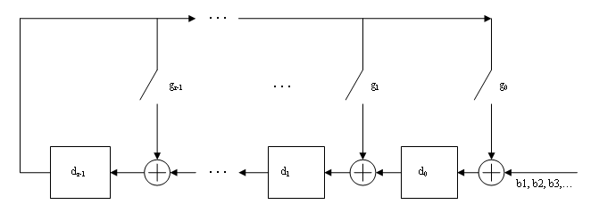
Bits enter the linear feedback shift register (LFSR) from the lowest index bit to the highest index bit. The sequence of input message bits represents the coefficients of a message polynomial in order of decreasing powers. The message vector is augmented with r zeros to flush out the LFSR, where r is the degree of the generator polynomial. If the output from the leftmost register stage d(1) is a 1, then the bits in the shift register are XORed with the coefficients of the generator polynomial. When the augmented message sequence is completely sent through the LFSR, the register contains the checksum [d(1) d(2) . . . d(r)]. This is an implementation of binary long division, in which the message sequence is the divisor (numerator) and the polynomial is the dividend (denominator). The CRC checksum is the remainder of the division operation.
Direct CRC Algorithm
This block diagram shows the direct CRC algorithm.
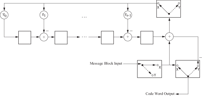
Where Message Block Input is and Code Word Output is
The initial step of the direct CRC encoding occurs with the three switches in position X. The algorithm feeds k message bits to the encoder. These bits are the first k bits of the code word output. Simultaneously, the algorithm sends k bits to the linear feedback shift register (LFSR). When the system completely feeds the kth message bit to the LFSR, the switches move to position Y. Here, the LFSR contains the mathematical remainder from the polynomial division. These bits are shifted out of the LFSR and they are the remaining bits (checksum) of the code word output.
References
[1] Sklar, Bernard. Digital Communications: Fundamentals and Applications. Englewood Cliffs, NJ: Prentice-Hall, 1988.
[2] Wicker, Stephen B., Error Control Systems for Digital Communication and Storage. Upper Saddle River, NJ, Prentice Hall, 1995.
Extended Capabilities
Version History
Introduced in R2024a
See Also
Functions
Blocks
You can also select a web site from the following list:
Americas
- América Latina (Español)
- Canada (English)
- United States (English)
Europe
- Belgium (English)
- Denmark (English)
- Deutschland (Deutsch)
- España (Español)
- Finland (English)
- France (Français)
- Ireland (English)
- Italia (Italiano)
- Luxembourg (English)
- Netherlands (English)
- Norway (English)
- Österreich (Deutsch)
- Portugal (English)
- Sweden (English)
- Switzerland
- United Kingdom (English)