
From Idea to MCU Deployment: Applying Tiny Machine Learning to FOC for PMSMs
Danilo Pau, STMicroelectronics
Field-oriented control (FOC) is an efficient technique for controlling permanent magnet synchronous motors (PMSMs), managing torque and speed by decoupling stator current into orthogonal components: direct axis current (Id) and quadrature axis current (Iq). Modeled in Simulink®, FOC systems use two proportional-integral-derivative (PID) controllers. The first PID controller regulates speed by comparing reference speed with measured speed and outputs reference current Iq. The second PID controller takes the reference currents and measured currents to output direct and quadrature voltages (Vd and Vq). However, PID control can result in suboptimal performance due to deviations and overshoot in the reference current Iq.
To enhance FOC performance, this talk proposes a two-step approach. Using MATLAB® tools for AI, a tiny neural network (NN) was devised and integrated to correct deviations in the reference current Iq generated by the speed PID controller. The NN is trained, pruned, and quantized using MATLAB tools for AI on data extracted from use cases to predict errors and provide corrective signals. These signals are added to the PID controller's output, resulting in near-optimal reference current Iq with minimized deviation and overshoot. The NN's inputs include multiplexed signals of reference speed, measured speed, and the initial reference current generated by the PID controller. The corrected Iq, along with the Id reference (maintained at zero for maximum electromagnetic torque), is then used by a secondary PID controller to generate quadrature (Vq) and direct (Vd) voltage commands, which are transformed via a Park transformation and utilized by an inverter to control a 4-pole pairs PMSM.
To study the deployability of the tiny NN-enhanced controller, inference time and memory footprint will be tested using the ST Edge AI Developer Cloud platform. This ensures the NN is deployable and performs well with respect to real-time PMSM control requirements.
Published: 6 Nov 2024
Hi, everybody. My name is Danilo Paul from STMicroelectronics. And today, I would like to talk a little bit about what does it take to bring an idea in the field of machine learning to a full microcontroller deployment with specific reference to how to apply machine learning to motor control for electric vehicles.
So first of all, why this is interesting for you and for me as well? Because the challenge here is to apply AI to motor control. And we all know that field-oriented control are well-deployed in this field. However, when introducing AI in the motor control, then we need to make sure that efficiency, accuracy, execution, speed are kept or even improved. And these require a huge understanding of both AI, but as well as a motor control.
And the combination of STMicroelectronics and MathWorks AI tool provide a perfect combination in order to build a methodology, which should be very simple for everyone to use in order to deploy on specific use cases on microcontrollers.
So let's review how this can be achieved. First of all, a few key words I would like you to remember-- productivity, interoperability, development, journey, non-linear control, FOC, Field-Oriented Control, automation, idea, embedded system, permanent magnetic synchronous motor. These are keywords which are important to center the attention on this presentation.
But let's go through the methodology. The methodology is very important, because it is above the problem, and allow us to reuse what we are going to speak, also in other fields.
First of all, we start with that acquisition. That acquisition, we did using the MATLAB and Simulink tools from MathWorks. Essentially, we wanted to mobilize the PMSM Field-Oriented Control model, and then define a few case studies in order to challenge the FOC under variable speeds, and then get data enough in order to move to the second step where we wanted to modelize neural network, but with the constrained resource available, so what we call tiny neural networks, in order to compensate drift, which are affecting the PID-based control under variable and challenging speed changes, and then make sure that the device, the neural network, is deployable.
So while designing the neural network using the MATLAB tool, also using the ST Edge AI Developer Cloud in order to prove that it's deployable ahead of any further development, which means, for example, ahead of training. And then we want to apply as many as optimization as possible using the MATLAB facilities-- for example, hyperparameter optimization, pruning-- in order to achieve a model which is tiny and still accurate and easy to deploy.
And then for the deployment, we would like to use the ST Edge AI Developer Cloud, which automatically import and deploy in an optimized way tiny neural network in order to profile the complexity, memory, footprint, execution time, and benchmark the capabilities of the different hypotheses, the different neural networks, and then loop back to the previous steps, modeling the tiny neural network, until all the process-- modeling, optimize, and deploy-- converge to an acceptable result.
So let's review a little bit key concept about the application context I am talking about-- Permanent Magnet Synchronous Motor. We have the rotor. The rotor is vested with permanent magnets.
And there is a stator. The stator is characterized by windings in which sinusoidal electric current flows. And these create an electromagnetic force which interact with the magnetic field created by the permanent magnets on the rotor.
And this allows exchange of forces in order to move the rotor. And vice versa, the rotor can also induce an electric current. So if we have a coil and we let a sinusoidal current to flow in the coil, essentially one directional vector, which represents the magnetic field, will oscillate up and down due to the sinusoidal nature of the electric current. This is well known by the theory.
However, if we have two coils, then what we are composing in the space is a rotating vector. But then if we have three phases, three windings, then we generate a vector which moves in the space, in the 3D space. And this is what we shall control in order to move the rotor properly.
However, if we change reference system, and then we are solid with the rotor, then we can induce a quadrature indirect force. And here, the goal is to maximize the quadrature force and to minimize the D force.
So you see that we have two contrasting needs to create a 3D vector, thanks to the sinusoidal current flows on the windings, but on the other side to transmit energy to the rotor in order to move it, and by controlling the Q and D force. So in order to simplify all that control, the field-oriented control is the way to make it, and in particular to make it using PID.
Now, what is important is that we want to move from a time-varying three-phase system in the rotor reference frame-- sorry, in the three-phase system to a D Q time invariant components, which are much easier to control with respect to the time-varying three phase in the vector space. And for that to transform our fundamental, which are well known, the Clark and Park transform and their inverse transform.
So if we put all together in a block diagram, on the right you see the block diagram which is used to control the PMSM motor. And these type of control is particular appealing because it allows to manage very high top speed with a very high energy efficiency, depending on the between 97% and 99.5%. And this is essential to the battery electric vehicle, which all we are experiencing in our daily life.
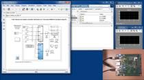
So let's move to the Simulink model. First of all, we adopted a which is very easy and cheap and safe and effective for educational purpose. This is characterized by a motor, a tiny motor, which operates under a very small, little voltage, 11.1 volt, which is well-suited to be controlled by an STM32 application board.
This is the X-NUCLEO IHM07M1. And in particular, it has been used to parameterize the Simulink model. Simulink model, which is available on GitHub, so you are invited to download it and to use it. And it was the model that we created in Simulink for the sake of this study.
Obviously, many more resources are available in MathWorks Help Center, so I invite you also to get them in order to study even more how to deal with the PMSM model. But then let's go to the problem definition and the requirements.
First case study we set was to change the speed two times a second in order to challenge the IP controller, and to let it produce a poor, dynamic and sluggish response. This also created significant deviations which are highlighted in red, in circles in red.
So you have the reference speed in red, which is the ideal speed, we would like to induce on the motor and the measured speed. There are clearly overshoots, which are characterizing the measure of the speed. And if we even push further, these stimulus, up to 10 times a second, clearly the PID is significantly failing with trying to stabilize this behavior, because a lot of non-linearities are introduced.
And these are shown in the blue lines, which represent the speed and the quadrature current, which clearly highlight the not well capability of the PID to cope with these changes. And then obviously we would like to find a solution, but a solution which is deployable on what? On my own embedded microcontroller.
Here, I'm showing two families, the Stellar family, which is automatic grade, and the STM32 family, different type of microcontroller with different speed, 300 and 170 megahertz, with different embedded memory. But definitely any solution we would like to find shall be deployable on such tiny devices.
So what is the approach devices? Essentially, we would like to generate through a tiny neural network a correction factor, which has to be added to the uncompensated reference current in order to generate a compensated reference current. So here, the challenge is to design a neural network which is capable to achieve this target, which was fed by the speed measured and the compensated reference current.
The solution that we devised in MATLAB, and which can be visualized as on the left part of this slide, is a 1,400 neural network, which is a forward neural network composed by fully connected layers with split and branches. And you see the visualization on the left part, which is through MATLAB, and the visualization at the center through the ONNX model, which has been supported. A lot of data have been generated through the methodology, say, in order to avoid overfit, and in order to create a significant ratio to order of magnitude between the number of samples available and the weights of the neural network.
So let's move to the results. The results, case 1, two changes in one second about the speed. So what we saw was that max deviation, average deviation and max overshoot. On the left-- the issues that we found. On the right-- the behavior that we compensated.
Clearly, there was a 10% increase in max deviation; however, 60% reduction in the average deviation; and up to 87%, 89% in term of reduction of the maximum overshoot.
Case 2, the max deviation in this case was marginally decreased by 1.65%; average deviation, 16.7% reduction; 68% reduction to the max overshoot.
Then we wanted to play with hyperparameter optimization. You know that MATLAB makes available a Bayesian approach, which is very convenient. And through iterations, we were looking to the best mean squared error in order to devise a reduced parameter network.
And the results were the following. The trainables were reduced, case 1, by 50%, case 2 by 75%. However, in case 1, the max overshoot was increased by 100%, and the average deviation by 58%.
On case 2, on the average deviation, there was no change. However, there was a dramatic increase in the max overshoot-- 1,450, which is not acceptable. So a significant reduction in the parameters down to 670 or 340 was nice to achieve, but however at a cost in term of performances that were not acceptable.
And therefore, we played also with the pruning capability made available by MATLAB. Here, the trainable were reduced, case 1 and case 2, respectively, by 37% and 57%. However, we had a marginal increase in max deviation and a significant deviation in the max overshoot-- in case 1, 100%. And also, this was significant-- 62% in the case 2. So pruning was quite effective.
Then let's review what were the cost of deploying such variants of the tiny neural network on the microcontroller. Here, we use the ST Edge AI Developer Cloud. So it's freely accessible and you can log in, and essentially you can have wide access to different microcontrollers, so STM32 family, Stellar family, the STM32 MP2, and also the inertial sensor provided by ST.
So these are very heterogeneous type of hardware. Beyond the scene, there is a unified core technology that essentially, through a number of unified processes, take a pre-trained neural network and generate very optimized C code in performances and memory usage, without you to need and crafting anything, and also support quantization, or through the ONNX Runtime or through TFLite, a well-known procedure.
And these are the results. So in bold highlight, the best results we had. For example, the lowest amount of libraries required to support this tiny neural network in case 1 were on the HPO model, even if it was not accurate. While on the pruned model, we had to pay a little bit more, 20 kilobytes.
The memory about the activation was very tiny, because the network is very tiny. And it was just 148 bytes. But the library to be loaded in the RAM was 10 kilobytes.
Then the best speed that we achieved was close to 145 microseconds with the NUCLEO G4, and higher speed mainly due to the different clock speed between the two, 170 megahertz, 300 megahertz with the Stellar too. So we were close to 70 microsecond. On the pruned model, 232 microsecond, and 100 microseconds, respectively, for the STM32 G4 and the Stellar E1.
And obviously we did also the same exercise for the quantization using the post-training quantization procedure made available by the ST Edge Developer Cloud. And here we had a very tiny weight footprint. However, this is subject of further optimization, which will be in the future work.
Equivalent comments can be done for case 2, more or less the top speed we achieved was 61 microseconds using the Stellar E1. However, I don't think this is enough. And so this allows me to introduce the future work and to conclude the presentation.
So first of all, you saw that by applying the neural network in the FOC for compensating the non-linearity induced by the PID can be achieved with the tiny neural network. And I think this approach can be extended also to other PIDs which are embodied in the FOC. So ideally, we would like to achieve an approach with a unified, tiny neural network put in the FOC.
The second challenge to be achieved in the future is what if we close the loop in 10 microseconds with a control speed of 100 kilohertz? So in that case, we need to accelerate the execution speed. And this is a subject, for example, for hardware acceleration in the future.
Useless to say, these things has to be tested on the field with real PMSM motor, not the one that I used for educational purposes. And obviously introduce new cases. The use cases I introduced were actually to challenge the PID in order to see how it coped with non-linearity and to justify the introduction of the neural network.
Quantization was not explored at the best. It was just an initial exercise. We used 8-bit quantization. Maybe other bit depth could be studied.
So I am at the end of the presentation. Thank you so much for your attention. It was really a big pleasure for me to be invited by MathWorks in this presentation. And I am very grateful for this opportunity.
For any further question, I remain available. And you also can write me to danilo.pau@st.com for further interaction. Thank you so much.
[MUSIC PLAYING]
Related Products
Learn More
Featured Product
Deep Learning Toolbox


Select a Web Site
Choose a web site to get translated content where available and see local events and offers. Based on your location, we recommend that you select: United States.
You can also select a web site from the following list
Americas
- América Latina (Español)
- Canada (English)
- United States (English)
Europe
- Belgium (English)
- Denmark (English)
- Deutschland (Deutsch)
- España (Español)
- Finland (English)
- France (Français)
- Ireland (English)
- Italia (Italiano)
- Luxembourg (English)
- Netherlands (English)
- Norway (English)
- Österreich (Deutsch)
- Portugal (English)
- Sweden (English)
- Switzerland
- United Kingdom (English)