NR HDL Downlink Signal Measurements
This example shows how to perform EVM measurements and SSB signal quality measurements for 5G downlink signals. The example performs downlink measurements on the resource grid outputs of a practical receiver designed for HDL code generation.
Evaluating the quality of downlink signals is a key component of designing and deploying 5G networks. This example performs error vector magnitude (EVM) and signal synchronization block (SSB) quality metrics measurements. The EVM measurements are implemented following the guidance presented in IEEE 1765-2022, IEEE Recommended Practice for Estimating the Uncertainty in Error Vector Magnitude of Measured Digitally Modulated Signals for Wireless Communications. The SSB signal quality metrics are implemented following the definitions in the 5G NR standard.
The measurements are performed on the outputs from the Simulink® models shown in this example. The models are fixed-point HDL-optimized implementations of a 5G receiver that can perform synchronization and downlink resource grid demodulation for 5G NR FR1 and FR2. This example is one of a related set, for more information see NR HDL Reference Applications Overview.
File Structure
This example uses these files.
Simulink models
nrhdlSIB1Demodulation.slx: This Simulink model references thenrhdlDDCCoreandnrhdlGridDemodulationCoremodels to simulate wideband grid demodulation.nrhdlSIB1Recovery.slx: This Simulink model combines the processing of the SSB detector, SSB decoder, grid demodulator, CORESET0 decoder, and SIB1 decoder into an integrated model illustrating the complete wideband grid recovery process. This model references thenrhdlDDCCore,nrhdlSSBDetectionCore,nrhdlSSBDecodingCore,nrhdlPolarDecodingChainCore,nrhdlGridDemodulationCore,nrhdlCORESET0DecodingCore, andnrhdlLDPCDecodingChainCoremodels.nrhdlDDCCore.slx: This model implements a DDC to create sample streams for SIB1 and SSBs.nrhdlSSBDetectionCore.slx: This model implements the SSB detection algorithm.nrhdlSSBDecodingCore.slx: This model implements the SSB decoding algorithm.nrhdlPolarDecodingChainCore.slx: This model implements the common polar decoding chain.nrhdlGridDemodulationCore.slx: This model implements the grid demodulation algorithm.nrhdlCORESET0DecodingCore.slx: This model implements the CORESET0 decoding algorithm.nrhdlLDPCDecodingChainCore.slx: This model implements the SIB1 LDPC decoding algorithm.
Simulink data dictionary
nrhdlReceiverData.sldd: This Simulink data dictionary contains bus objects that define the buses contained in the example models.
MATLAB code
runNRGridDemodulationModel.m: This script uses the MATLAB reference to implement the MIB recovery algorithm, then runs thenrhdlSIB1DemodulationSimulink model to demodulate the wideband grid. The script then performs EVM measurements on the demodulated grid.runNRGridRecoveryModel.m: This script uses the MATLAB reference to perform the search mode of the SSB detection algorithm, then runs thenrhdlSIB1RecoverySimulink model to demodulate and decode the SSB, and then demodulate the wideband grid. The script then performs downlink signal quality measurements on the demodulated SSB grid, and EVM measurements on the wideband grid.nrhdlexamples: Namespace containing the MATLAB reference code and utility functions for verifying the implementation models.
IEEE 1765-2022 EVM Measurements
EVM is a measurement used to determine the distortion introduced to a digital signal by a transmitter or receiver implementation. The EVM of a 5G downlink signal at a receiver can be calculated by performing OFDM demodulation to recover the resource grid, and then comparing the symbols of the demodulated resource grid to the original transmitted resource grid. The example follows the recommended practices provided by the IEEE 1765-2022 standard. The standard defines algorithms for determining the EVM from a device under test (DUT), and focuses on the process of validating a practical recevier. In this example the DUT is the Simulink model implementing wideband grid demodulation for HDL code generation. Two methods of EVM measurement are shown: baseline EVM and baseline residual EVM. The measurement procedures include the recommendations within the EVM comparison with specialized receiver section of the standard, which allows for the EVM measurements to be computed with the practical synchronization steps of the receiver included.
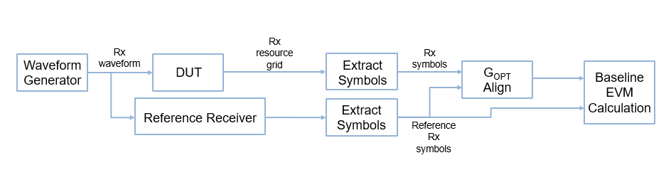
Baseline EVM
The experimental setup for calculating the baseline EVM is shown. The waveform generator uses 5G Toolbox™ to generate a test waveform containing PDSCH data for measurement, and an SSB for practical synchronization. The waveform generator also outputs the transmitted resource grid symbols which provides the basis for comparison in this measurement. The DUT processes the waveform to demodulate the resource grid, and extracts the symbols containing the PDSCH data. The received and transmitted symbols are aligned for optimal gain and phase across all symbols, and the EVM calculation is performed.

Baseline Residual EVM
The diagram shows the experimental setup for calculating the baseline residual EVM. The method for obtaining the received PDSCH symbols is the same as for the baseline EVM measurement. However, instead of using the transmitted symbols directly from the waveform generator, a pre-verified reference receiver is used to generate the reference symbols. The symbols from both the DUT and the reference receiver are gain and phase aligned and the baseline EVM calculation is performed. This calculation measures the residual error between the two receiver implementations and improves the robustness of results when the measured symbols are distorted by a channel or other impairments before the receiver itself.
To demonstrate the usage of the two EVM measurements consider the verification of two receiver designs, DUT A and DUT B, using a reference receiver for comparison. The plot shows a constellation diagram of the symbol received by each receiver, alongside the known transmitted symbol (Tx Sym), and the unknown true position of the received symbol (True Rx Sym) that an ideal receiver would measure. The baseline EVM for DUT A, DUT B, and the reference receiver are similar because they are approximately equidistant from the transmitted symbol. However, the baseline residual EVM is significantly improved for DUT A in comparison with DUT B, because DUT A is closer to the true received symbol. This shows how baseline residual EVM confirms the improved accuracy of the receiver in this case.

5G NR SSB Signal Quality Measurements
The 5G standard defines a set of measurement capabilities in TS 38.215 to analyze the quality of received downlink signals for user equipment (UEs). Four of these measurements are implemented in this example:
RSSI - Received signal strength indicator
RSRP - Reference signal received power
RSRQ - Reference signal received quality
SINR - Signal to interference & noise ratio
The measurements are performed using the nrhdlexamples.ssbMeasurements function on the demodulated SSB resource grid acquired during the synchronization process. The RSSI, RSRP, and RSRQ measurements are calculated by the nrSSBMeasurements (5G Toolbox) function. The SINR is calculated by estimating the noise power from the null resource elements of the SSB, and dividing the result by the RSRP measurement.
Wideband Grid Demodulation
To perform EVM measurements the DUT must output the demodulated resource grid containing the received symbols. The figure shows the nrhdlSIB1Demodulation model. The top level of the model reads the signals from the MATLAB base workspace, passes them to the SIB1 Demodulation subsystem, and writes the outputs back to the workspace. This section describes how to use the SIB1 demodulation MATLAB reference and Simulink implementation from the Hardware Accelerators for NR SIB1 Recovery example to perform customizable wideband grid demodulation.
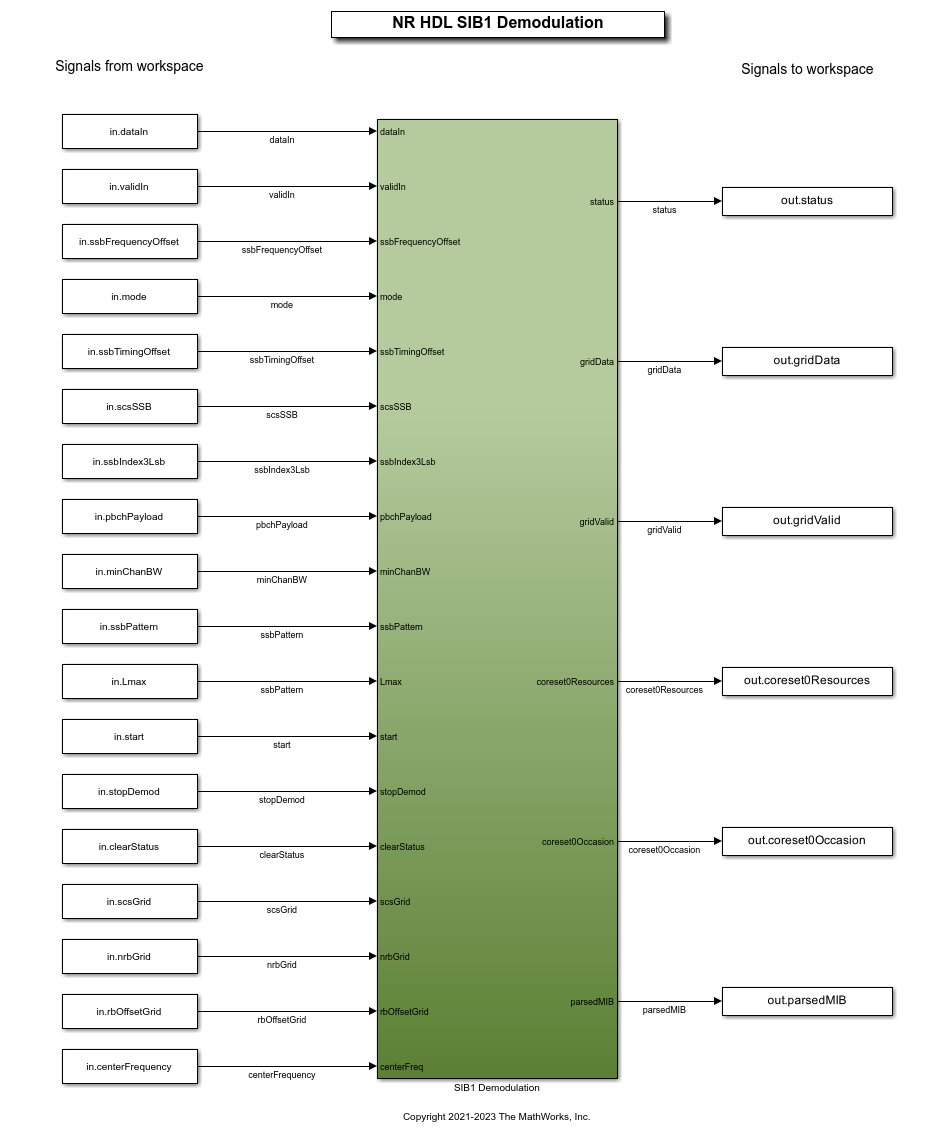
The design supports both SIB1 and wideband modes and is runtime configurable to switch between them. The current mode of the grid demodulation is controlled by the mode input port. When the mode input port is 1 the algorithm performs wideband demodulation with the configuration from three additional ports. For the SIB1 use case the subcarrier spacing (SCS), number of resource blocks (NRB), and the time and frequency allocation is determined by decoding the MIB. To allow for customizable wideband demodulation the scsGrid, nrbGrid and rbOffsetGrid input ports specify the SCS, NRB, and frequency position of the demodulated grid. The frequency position is specified as a resource block offset from the center of the SSB. The final frequency offset applied to the recevied signal includes the specified frequency position, the subcarrier spacing offset of the SSB relative to the resource grid, kSSB, and the measured frequency offset of the SSB. The timing occasion of the demodulation is fixed and it starts on the 5G framehead and continues until the stopDemod port is asserted. The specification for each port is shown.
mode: 1-bit unsigned value that controls the grid demodulation mode. 0 indicates SIB1, and 1 represents wideband.
scsGrid: 2-bit unsigned value specifying the subcarrier spacing used for the wideband grid mode. The values 0, 1, 2, and 3 represent SCS 15, 30, 60, and 120 kHz respectively.
nrbGrid: 9-bit unsigned value specifying the bandwidth of the wideband grid demodulation in resource blocks.
rbOffsetGrid: 9-bit unsigned value specifying the wideband grid frequency offset in resource blocks.
stopDemod: 1-bit control signal to stop the wideband grid demodulation mode operation.
The GridDemodulationCore/Configuration subsystem in the nrhdlGridDemodulationCore model switches between the SIB1 configuration from the MIB and the wideband configuration from input port based on the mode input, and computes the timing of the framehead.

Simulation Setup
The diagram shows the simulation setup implemented by this example. 5G Toolbox functions generate a test waveform. MATLAB reference code then performs the steps required for MIB recovery - SSB search, demodulation, and decoding. The results provide the input data for the wideband grid demodulation stage. The same input is passed to both MATLAB and Simulink implementations of grid demodulation, and the output grids are directly compared. The test bench computes the EVM on the wideband resource grid from the Simulink simulation using the baseline and baseline residual algorithms. The baseline residual EVM uses the nrOFDMDemodulate function from 5G Toolbox as the reference receiver.

The Test bench options section of the runNRGridDemodulationModel script includes these variables to configure the simulation:
simulationCase: specifies the configuration of the generated waveform. The simulation cases demonstrate the SCS options 120, 60, 30 and 15 for the generated PDSCH. The table shows the set of simulation cases:
    Simulation Case    Subcarrier Spacing    NRB     PRB Set      Slot Allocation    Period Allocation    SNR dB    SSB Pattern    Strongest SSB index    Lmax
    _______________    __________________    ___    __________    _______________    _________________    ______    ___________    ___________________    ____

    "SimCase EVM 1"           120            264      0     99        2    79               80             100       "Case D"               0              64
    "SimCase EVM 2"            60            264    164    263        2    39               40             100       "Case D"               0              64
    "SimCase EVM 3"            30            264    107    156        2    19               20             100       "Case C"               0               8
    "SimCase EVM 4"            15            264     10    253        2     9               10             100       "Case A"               0               8
numSubFrames: specifies the number of 1 ms subframes generated as input stimulus.
widebandCfg: specifies the configuration of the wideband grid demodulation bandwidth and frequency shift. The SCS of the demodulated grid is set to match the generated PDSCH transmission.
Simulation
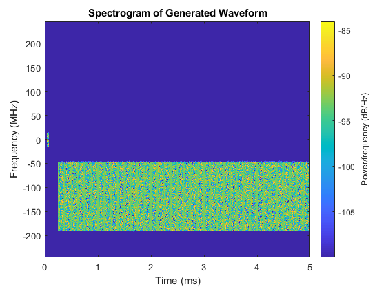
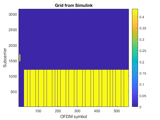
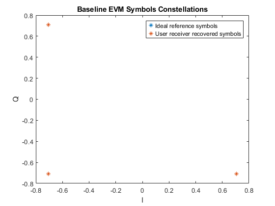
Use the runNRGridDemodulationModel script to run a wideband grid demodulation simulation. The script displays its progress at the MATLAB command prompt, and produces plots of inputs and outputs for analysis. This example shows the results of running "SimCase EVM 1". The resource grids produced by MATLAB and Simulink are displayed along with the difference between them and their relative mean square error (MSE). The two EVM measurements for the Simulink grid are displayed. The constellations of the aligned received and reference symbols are plotted.
runNRGridDemodulationModel;
Generating test waveform.
Searching for SSBs using MATLAB reference.
Demodulating the strongest SSB using MATLAB reference.
Decoding the demodulated SSB using MATLAB reference.
Demodulating the grid using MATLAB reference.
Demodulating the grid using Simulink model.
Running nrhdlSIB1Demodulation.slx
### Searching for referenced models in model 'nrhdlSIB1Demodulation'.
### Found 2 model reference targets to update.
### Starting serial model reference simulation build.
### Model reference simulation target for nrhdlDDCCore is up to date.
### Model reference simulation target for nrhdlGridDemodulationCore is up to date.

Build Summary

0 of 2 models built (2 models already up to date)
Build duration: 0h 0m 1.6711s
..........
MATLAB and Simulink grids relative MSE : -88.9792 dB
Baseline EVM RMS: 0.0021424%
Baseline Residual EVM RMS: 0.0022525%


Wideband Grid Recovery
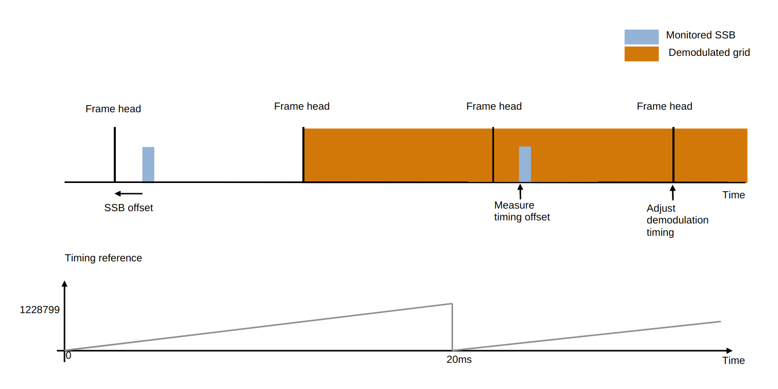
Wideband grid recovery uses the nrhdlSIB1Recovery model from the NR HDL SIB1 Recovery for FR2 example to recover the grid from a baseband 5G signal. This model integrates the HDL implementations for performing cell search, MIB recovery, SIB1 recovery, and wideband grid recovery into a single design. When the design is used for wideband grid recovery it searches for SSBs, demodulates a chosen SSB, decodes the MIB and then begins demodulating the wideband grid. The diagram shows the timing and synchronization between the SSB detection and decoding and the wideband demodulation. After the first SSB is decoded the framehead timing is computed and when the time is reached the demodulation begins. The detector monitors the SSB every 20ms and measures the timing delta between the subsequent detections. The timing adjustment is supplied to the grid demodulator and applied on the next framehead.
Operations
The design operates in one of two modes - search or demodulation. A full wideband grid recovery consists of one or more searches followed by a demodulation operation. The operations extend the MIB recovery operations in the NR HDL MIB Recovery example.
1. Search Mode
The search mode behavior is unchanged from the cell search and MIB recovery design. The SSB detector searches for SSBs at the specified subcarrier spacing and frequency offset by correlating against each PSS sequence. The operation outputs a list of the detected SSBs, defined by a timing offset and PSS sequence ID.
2. Demodulation Mode
The demodulation mode operation is extended from the MIB recovery design by including the grid demodulator. The decoded MIB from the SSB decoder is used to locate the framehead timing of the received waveform and the grid demodulation inputs are used to demodulate the resource grid. The demodulation starts on the framehead after the MIB is decoded. Wideband grid demodulation uses repeat demodulation mode for the SSB detector to monitor the signal timing and provide tracking corrections to the grid demodulator. Timing adjustments are applied on the framehead after each MIB is decoded.
Simulation
Use the runNRGridRecoveryModel script to run a wideband grid recovery simulation in the nrhdlSIB1Recovery model. After recovering the SSB and wideband resource grids from Simulink, the script runs the SSB signal quality measurements on the demodulated SSB grid. The script also runs the baseline EVM and baseline residual EVM measurements on the recovered wideband resource grid from Simulink. The Simulation setup and example results from the EVM and SSB measurements are shown.

    Measurement     Value
    ___________    _______

      "RSRP"        10.203
      "RSSI"         33.37
      "RSRQ"       -10.157
      "SINR"        52.505

Baseline EVM RMS: 0.041271%
Baseline Residual EVM RMS: 0.041242%
Related Topics
- 5G NR Downlink Signal Measurements Using AMD RFSoC Device (SoC Blockset)
Select a Web Site
Choose a web site to get translated content where available and see local events and offers. Based on your location, we recommend that you select: United States.
You can also select a web site from the following list
Americas
- América Latina (Español)
- Canada (English)
- United States (English)
Europe
- Belgium (English)
- Denmark (English)
- Deutschland (Deutsch)
- España (Español)
- Finland (English)
- France (Français)
- Ireland (English)
- Italia (Italiano)
- Luxembourg (English)
- Netherlands (English)
- Norway (English)
- Österreich (Deutsch)
- Portugal (English)
- Sweden (English)
- Switzerland
- United Kingdom (English)
Asia Pacific
- Australia (English)
- India (English)
- New Zealand (English)
- 中国
- 日本Japanese (日本語)
- 한국Korean (한국어)