HDL Code Generation for Filtered OFDM (F-OFDM) Transmitter
Filtered OFDM (F-OFDM) applies a filter to the symbols after the IFFT in the transmitter to improve bandwidth while maintaining the orthogonality of the complex symbols. This example implements a transmitter F-OFDM for HDL code generation. The example shows how to go from a MATLAB® reference model to an HDL-optimized Simulink® model. It includes converting from double to fixed-point types, and minimizing the resource use of the design on an FPGA.
Refer to F-OFDM vs. OFDM Modulation for comparison between OFDM and F-OFDM waveforms.
System Parameters
Set the desired F-OFDM properties.
NDLRB             = 108;
WaveformType      = 'F-OFDM';
SubcarrierSpacing = 60*1e3; %Hz
CellRefP          = 1;
CyclicPrefix      = 'Normal';
FilterLength      = 513;
ToneOffset        = 2.5000;
CyclicExtension   = 'off';
Call the h5gOFDMInfo function to calculate F-OFDM parameters. The method calculates FFT length, cyclic prefix lengths and number of subcarriers.
genb = struct('NDLRB', NDLRB,...
              'WaveformType', WaveformType,....
              'SubcarrierSpacing', SubcarrierSpacing*1e-3,...
              'FilterLength', FilterLength,...
              'ToneOffset', ToneOffset,...
              'CellRefP', CellRefP,...
              'CyclicPrefix', CyclicPrefix,...
              'CyclicExtension', CyclicExtension);
info = h5gOFDMInfo(genb);
Generate a Grid of Input Data
QAMModulation    = '64QAM';
TotSubframes     = 5;
[txgrid, bitsIn] = generateOFDMGrid(genb,info,QAMModulation,TotSubframes);
Reference MATLAB Model
The reference model runs a floating-point F-OFDM system and plots the spectrum. Use the reference model to compare against the fixed-point model that supports HDL code generation.
[txSig_ref,txinfo] = h5gOFDMModulate(genb,txgrid);
Model the channel by adding noise to the signal.
snrdB = 18;
S = RandStream('mt19937ar','Seed',1);
rxSig_ref = awgn(double(txSig_ref),snrdB,'measured',S);
The received signal must be synchronized and aligned. In real situations, the receiver includes symbol synchronization. In this example, the receiver corrects for the shift of the frame by the transmitter filter by  .
.
rxSig_ref_sync = circshift(rxSig_ref,-floor(FilterLength/2));
Recover data, calculate BER, and display constellation.
[constDiagRx, ber, rxgrid_ref] = FOFDM_Receiver(rxSig_ref_sync, bitsIn, genb,...
                                 QAMModulation, 'F-OFDM Reception (REF)');
disp(['F-OFDM Reception (REF)', ' BER = ' num2str(ber(1)) ' at SNR = ' num2str(snrdB) ' dB']);
constDiagRx(rxgrid_ref(:));
F-OFDM Reception (REF) BER = 0.0093548 at SNR = 18 dB
![]()
The spectrum shows clear improvement of out-of-band radiation of the subband signal, and increase in effective bandwidth.
FOFDMTransmitterHDLSpectrum(txSig_ref,txinfo,genb,'F-OFDM Spectrum (REF)');
![]()
Simulink Fixed-point Model
model = 'FOFDMTransmitterHDLExample_FixPt';
load_system(model);
open_system([model, '/F-OFDM']);
![]()
To generate HDL from the model, fixed-point data type must be used instead of double. For 64-point QAM, at least 6 bits + 1 sign bit is needed. However, to achieve reasonable BER, the input word length must be increased, considering the FPGA's limitation. Multipliers in FPGAs have limited input word length. For example, Xilinx's DSP48 has 18*25-bit multiplier. For an optimal design, a wordlength is chosen so that all multipliers in the FFT and the filter are smaller than 18*25-bit multipliers. In this example, the FFT block uses the "Divide butterfly outputs by two" option. The input word length is 16 bits.
You can run the Simulink model with floating point data by setting WORDLENGTH=-1. However, this mode is not supported for HDL code generation.
WORDLENGTH = 16;
Set the number of fractional bits to WORDLENGTH - 2 bits to cover -1 <= Symbol <= 1.
FRACTIONLENGTH = WORDLENGTH - 2;
Generating OFDM Symbols
The input data to the IFFT is assumed to be a proper OFDM symbol and resides in a memory (OFDM Symbol subsystem in the model) that can be read by F-OFDM Subsystem. Therefore, the transmitter's sample rate depends on the data availability in the memory and FPGA clock frequency. If the data is available all the time, then the sample rate is limited to
 .
.
On the other hand, the required sample rate is calculated by  and it is equal to 122.88 Msps for this example. To achieve 122.88 Msps the clock frequency should be at least 135.36 MHz.
ifftin = generateOFDMSymbol(txgrid,info,genb);
Filter Design
The appropriate filter should have a flat passband over the subcarriers and sharp transition to minimize guard bands. It also needs sufficient stopband attenuation. A prototype filter  is used, where
  is a SINC function and
 .
.
fnum = generateFilterCoef(genb,info);
Simulation
Set up the model and run. Note that due to the system latency, the model needs to be simulated longer to collect enough data.
Nfft = info.Nfft;
CyclicPrefixLengths = info.CyclicPrefixLengths;
SymbolsPerSubframe = info.SymbolsPerSubframe;

STOPTIME = 4 * TotSubframes * info.SamplesPerSubframe;

sim(model);
txSig_fixpt = TX_WAVEFORM(1: size(txSig_ref,1));
Model the channel by adding some noise to the signal. Note that the same noise is used as in the reference MATLAB model.
S = RandStream('mt19937ar','Seed',1);
rxSig_fixpt = awgn(double(txSig_fixpt),snrdB,'measured',S);
Perform symbol synchronization, recover data, calculate BER, and display constellation.
rxSig_fixpt_sync = circshift(rxSig_fixpt,-floor(genb.FilterLength/2));

[constDiagRx,ber,rxgrid_fixpt] = FOFDM_Receiver(rxSig_fixpt_sync,bitsIn, ...
                                 genb, QAMModulation,'F-OFDM Reception (FIXED-POINT)');
disp(['F-OFDM Reception (FIXED-POINT)',' BER = ' num2str(ber(1)) ' at SNR = ' num2str(snrdB) ' dB']);
constDiagRx(rxgrid_fixpt(:));
F-OFDM Reception (FIXED-POINT) BER = 0.0093975 at SNR = 18 dB
![]()
The spectrum shows even for fixed point a clear improvement of out-of-band radiation of the subband signal, and increase in effective bandwidth.
FOFDMTransmitterHDLSpectrum(txSig_fixpt,txinfo,genb,'F-OFDM Spectrum (FIXED-POINT)');
![]()
Simulink HDL-Optimized Model
The fixed point model uses a 513-tap filter in the time domain. This filter requires 2*513 multipliers since the output of IFFT is complex. Even when implemented using a symmetric filter it needs 513 multipliers which is too many multipliers for a normal size FPGA. To reduce the number of multipliers in the filter, the model filters in the frequency domain. A frequency domain FIR filter requires FFT of the input multiplied by FFT of the coefficients and then IFFT the result. The number of complex multipliers in this case is
 .
.
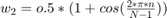
The frequency domain filter in this example uses 11 complex multipliers. Note that the actual number of real multipliers depends on FFT and IFFT block setting (Complex multiplication option) and word length. In the model, the time domain FIR filter is replaced by a frequency domain FIR filter implemented with an overlap-save architecture. Due to overlapping characteristic of the overlap-save architecture, the sample-rate is limited to
 .
.
Therefore, to achieve 122.88 Msps sample-rate for this example, the clock frequency must be at least 196.8 MHz.
model = 'FOFDMTransmitterHDLExample_HDLOpt';
load_system(model);
open_system([model, '/F-OFDM']);
![]()
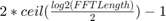
Set the length of the FFT for the filter. The length must be at least 2*FilterLength for frequency domain filtering. However, because it must process the whole OFDM symbol at once use Nfft for FFT length inside the filter. Then, calculate the FFT of the coefficients. Bit-reverse the result since the output of the FFT for the filter is bit-reversed.
filterFFTLen = Nfft;
fftFnum = bitrevorder(fft(fnum,filterFFTLen).');
For fixed-point input data, the output of the FFT inside the filter has a bit-growth = log2(Nfft) = 11 bits. To map most of the multipliers into DSP block in FPGA, limit the input word length. For example if DSP has a 25*18-bit multiplier, the WORDLENGTH must be 14 bits to achieve 25-bits output of the FFT inside the filter. Also, use 18-bit coefficients.
WORDLENGTH = 14;
FRACTIONLENGTH = WORDLENGTH - 2;
if WORDLENGTH > 0 %for fixed point data
    COEF_WL = 18;
    COEF_FR = COEF_WL - 2;
    fftFnum = fi(fftFnum, 1, COEF_WL, COEF_FR,'RoundingMethod','Nearest',...
              'OverflowAction','Wrap');
end
STOPTIME = 4 * TotSubframes * info.SamplesPerSubframe;

sim(model);
txSig_HDLOpt = TX_WAVEFORM_HDLOpt(1: size(txSig_ref,1));
Model the channel by adding some noise to the signal. Note that the same noise is used as in the reference MATLAB model.
S = RandStream('mt19937ar','Seed',1);
rxSig_HDLOpt = awgn(double(txSig_HDLOpt), snrdB, 'measured', S);
Perform symbol synchronization, recover data, calculate BER, and display constellation.
rxSig_HDLOpt_sync = circshift(rxSig_HDLOpt,-floor(genb.FilterLength/2));

[constDiagRx,ber,rxgrid_HDLOpt] = FOFDM_Receiver(rxSig_HDLOpt_sync,bitsIn,...
                                  genb, QAMModulation, 'F-OFDM Reception (HDLOPT)');
disp(['F-OFDM Reception (HDLOPT)',' BER = ' num2str(ber(1)) ' at SNR = ' num2str(snrdB) ' dB']);
constDiagRx(rxgrid_HDLOpt(:));
F-OFDM Reception (HDLOPT) BER = 0.0099992 at SNR = 18 dB
![]()
The spectrum shows even for fixed point a clear improvement of out-of-band radiation of the subband signal, and increase in effective bandwidth.
FOFDMTransmitterHDLSpectrum(txSig_HDLOpt,txinfo,genb,'F-OFDM Spectrum (HDLOPT)');
![]()
Generate HDL Code and Test Bench
Use a temporary directory for the generated files:
     systemname = 'FOFDMTransmitterHDLExample_HDLOpt/F-OFDM';
     workingdir = tempname;
You can run the following command to check the F-OFDM subsystem for HDL code generation compatibility:
checkhdl(systemname,'TargetDirectory',workingdir);
Run the following command to generate HDL code:
makehdl(systemname,'TargetDirectory',workingdir);
Run the following command to generate the test bench:
makehdltb(systemname,'TargetDirectory',workingdir);
Synthesis Result
The design was synthesized for Xilinx Zynq-7000 (xc7z045-ffg900, speed grade 2) using Vivado. This FPGA has 900 DSP48 slices and therefore, the fixed-point version of the design doesn't fit in this device. The HDL-optimized version of the design fits in this chip and achieves a clock frequency of 205.8 MHz which meets the required clock frequency of 196.8 MHz. The design uses 94 DSP48 (10%) and 24 block RAMs (4%).
Conclusion
In this example a Simulink fixed-point model was developed and optimized for hardware. The model minimized resource usage by optimizing use of DSP on the FPGA. Comparing the results of the floating-point model with the fixed-point model shows that 16-bit data has a similar bit error rate to the floating-point data.