Multi-Zone Metering
This example shows how to use the Image Statistics block to perform multi-zone metering to extract a region of interest (ROI).
There are numerous applications where the input video is divided into several zones, and the statistic is then computed over each zone. For example, many auto-exposure algorithms compute the difference in the mean intensity between zones. This allows the shutter controller logic to determine whether the image is under-exposed (overall low illumination), correctly-exposed (uniform illumination) or over-exposed (one or more ROIs have a larger mean).
Introduction
The MultizoneMeteringHDL.slx system is shown.

The green and red lines represent full-frame processing and pixel-stream processing, respectively. The color difference indicates the change in the image rate on the streaming branch of the model. This rate transition is because the pixel stream is sent out in the same amount of time as the full video frames and therefore it is transmitted at a higher rate.
In this example, the Pixel-Stream ROI extraction subsystem calculates the mean intensity value over 12 predefined ROIs in a frame and outputs the index number (1-12) that corresponds to the most illuminated ROI. The downstream Mask Selection subsystem accepts this index number and outputs the associated binary mask image. The binary mask image is applied to the source video to display only the most illuminated ROI, and mask off the other 11 ROIs. The Delay block at the top level of the model is used to match the latency introduced by pixel-stream processing.
One frame of the source image, the binary mask image, and the ROI output, are shown from left to right in the diagram below.

You can generate HDL code from the Pixel-Stream ROI Extraction subsystem.
Video Source
The video format is 240p. Each frame consists of 240 lines and 320 pixels per line. In this example, video frames are divided into 12 non-overlapping rectangular ROIs, denoted as ROI number 1 to 12, as shown in the diagram below. Each ROI includes one key of the input keypad image.

ROI number 1 has a 107-pixel width and a 60-pixel height, and the (x,y) coordinate of its top-left pixel is (1,1). ROI number 2 has a 107-pixel width and a 60-pixel height, and the coordinate of its top left pixel is (108,1), and so on. The first frame of the input video has brighter pixels within ROI number 1, as shown above. The second frame has brighter pixels within ROI number 2, and so on.
Frame To Pixels: Generating a Pixel Stream
Frame To Pixels converts a full-frame image to a pixel stream. To simulate the effect of horizontal and vertical blanking periods found in real life hardware video systems, the active image is augmented with non-image data. For more information on the streaming pixel protocol, see Streaming Pixel Interface. The Frame To Pixels block is configured as shown:
![]()
The Number of components field is set to 1 for grayscale image input, and the Video format field is 240p to match that of the video source.
In this example, the Active Video region corresponds to the 240x320 matrix of the source image. Six other parameters, namely, Total pixels per line, Total video lines, Starting active line, Ending active line, Front porch, and Back porch specify how many non-image data will be augmented on the four sides of the Active Video. For more information, see the Frame To Pixels block reference page.
Note that the sample time of the Video Source is determined by the product of Total pixels per line and Total video lines.
Pixel-Stream ROI Extraction
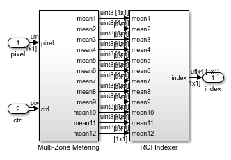
The Pixel-Stream ROI Extraction subsystem contains two subsystems, namely, Multi-Zone Metering and ROI Indexer.

The Multi-Zone Metering subsystem computes the mean intensity value over the 12 predefined ROIs. The resulting 12 mean values are passed to the downstream ROI Indexer subsystem. ROI Indexer outputs the index (1-12) of the ROI that has the maximum mean intensity value (or equivalently, the most illuminated ROI) among the 12 candidates.
The structure of the Multi-Zone Metering subsystem is shown in the diagram below.

The Multi-Zone Metering subsystem contains 12 identical ROIStatistic subsystems. Each instance of ROIStatistic calculates the mean intensity value over one ROI. All of the 12 ROIStatistic subsystems take pixel and ctrl as their first two inputs. The remaining four inputs specify which ROI this subsystem works on and they are different from one subsystem to another. For example, the ROIStaticstic1 subsystem focuses on ROI number 1 by accepting the (x,y) coordinate of the top left pixel (1,1), ROI width of 107, and height 60. Similarly, the ROIStaticstic12 subsystem focuses on ROI number 12, whose (x,y) coordinate of the top left pixel is (215,181), and whose width and height are 106 and 60, respectively.
The ROIStatistic1 - ROIStatistic12 subsystems share the same structure shown below.

It contains a ROI Selector block followed by an Image Statistics block. The ROI Selector block manipulates the control signal of the original 240p image, and constructs the control signals associated only with the ROI specified by (x,y) pair, ROIWidth, and ROIHeight.
Mask Selection
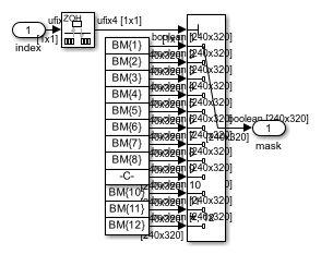
The structure of the Mask Selection subsystem is shown below.

Twelve mask images are available, corresponding to the 12 different ROIs. These mask patterns are shown as BM{1} to BM{12} in the above diagram. When you open the model, the model loads the predefined BM cell array into the workspace. Masks are binary images with 240p video format. For mask BM{n} (n=1,2,...,12), the ROI number n is filled with logical 1 pixels (white) and all the other 11 ROIs are filled with logical 0 pixels (black). Based on the index input (1-12), the Mask Selection subsystem outputs the associated binary mask image.
HDL Code Generation
To check and generate the HDL code referenced in this example, you must have an HDL Coder™ license.
To generate the HDL code, use the following command.
makehdl('MultizoneMeteringHDL/Pixel-Stream ROI Extraction')
To generate a test bench, use the following command. Note that the test bench generation takes a long time due to the large data size. You may want to reduce the simulation time before generating the test bench.
makehdltb('MultizoneMeteringHDL/Pixel-Stream ROI Extraction')