Edge Detection and Image Overlay with Impaired Frame
This example shows how to introduce impairments in order to test a design with imperfect video input.
When designing video processing algorithms, an important concern is the quality of the incoming video stream. Real-life video systems, like surveillance cameras or camcorders, produce imperfect signals. The stream can contain errors such as active lines of unequal length, glitches, or incomplete frames. In simulation, a streaming video source will usually produce perfect signals. When you use the Frame To Pixels block from the Vision HDL Toolbox™, all lines are of equal size, and all frames are complete. A video algorithm that simulates well under these conditions does not guarantee its effectiveness on an FPGA that connects to a real-world video source. To assess the robustness of a video algorithm under nonideal real-world video signals, it is practical to introduce impairments in the pixel stream.
This example extends the Edge Detection and Image Overlay example by manually masking off the leading control signals of a frame to resemble a scenario where the algorithm starts in the middle of a frame. Such test scenarios are necessary to prove robustness of streaming video designs.
It is beneficial to go over the Edge Detection and Image Overlay example before proceeding to this example.
Structure of the Example
The structure of this example is shown below, which closely follows the structure of the pixel-stream processing unit of the model in Edge Detection and Image Overlay.
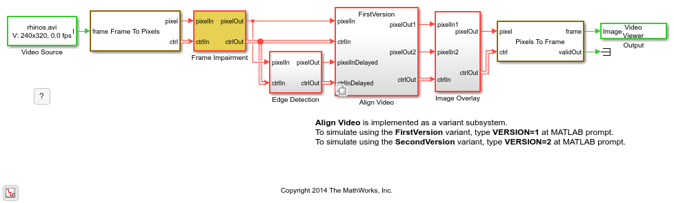
The Edge Detection subsystem implements a Sobel algorithm to highlight the edge of an image. The Align Video subsystem is used to synchronize the delayed output of the EdgeDetector with the original frame. Image Overlay weights and sums up the two time-aligned images.
This material is organized as follows. We first develop an Align Video subsystem that works well with perfect video signals. Then, we use the Frame Impairment subsystem to mask off the leading control signals of a frame to resemble a scenario where the algorithm starts in the middle of a frame. We will see that such impairment makes Align Video ineffective. Finally, a revised version of Align Video is developed to address the issue.
Align Video is implemented as a variant subsystem. You can use the variable VERSION in workspace to select which one of the two versions you want to simulate.
Note: Starting in R2017a the Pixel Stream Aligner block replaces the Align Video subsystem shown here. This new block makes setting the line buffer size and number of lines much easier and generates HDL code. In new designs, use the Pixel Stream Aligner block rather than the Align Video subsystem. For an example of how to use the block, see Edge Detection and Image Overlay.
First Version of Align Video
The following diagram shows the structure of the first version of the Align Video subsystem.
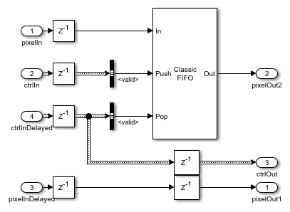
Align Video uses control signals to detect the active region of a frame. For more information on the streaming pixel protocol, see Streaming Pixel Interface.
The basic idea of aligning two pixel streams is to buffer valid pixels that come earlier into a FIFO based only on valid signals, and appropriately pop individual pixel from this FIFO based on the valid signal of the delayed pixel-stream.
Test Align Video Using Frame Impairment Subsystem
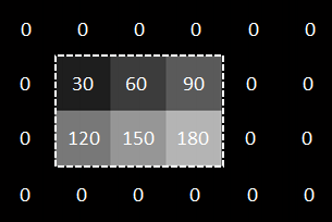
To illustrate how the Frame Impairment subsystem works, consider a 2-by-3 pixel frame. In the figure below, this frame is showed in the dashed rectangle with inactive pixels surrounding it. Inactive pixels include a 1-pixel-wide back porch, a 2-pixel-wide front porch, 1 line before the first active line, and 1 line after the last active line. Both active and inactive pixels are labeled with their grayscale values.
If the Frame To Pixels block accepts this 2-by-3 frame as an input and its settings correspond to the porch lengths shown above, then the timing diagram of the Frame To Pixels output is illustrated in the upper half of the following diagram.
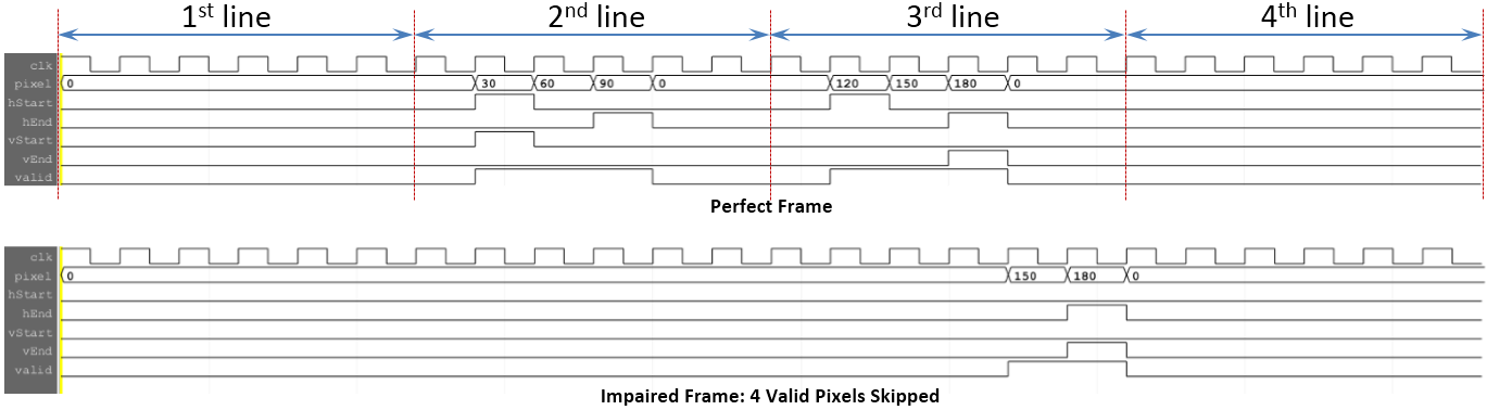
The Frame Impairment subsystem skips a configurable number of valid pixels at the beginning of the simulation. For example, if it was configured to skip 4 pixels of the example frame, the result would be as in the lower half of the timing diagram. We can see that by skipping 4 valid pixels, the three valid pixels on the second line (i.e., with intensity values of 30, 60, and 90), and the first valid pixel on the third line, are masked off, along with their associated control signals. Moreover, the Frame Impairment subsystem introduces two clock cycle delays. If we enter 0 pixels to skip, it just delays both pixel and ctrl outputs from Frame To Pixels by two clock cycles.
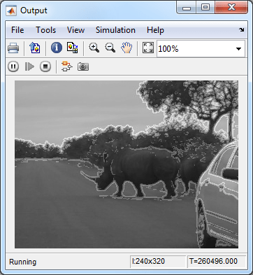
Double-click the Frame Impairment subsystem and ensure 'Number of valid pixels to skip' is set to 0. As mentioned before, this setting does not impair the frame, all it does is to delay both pixel and ctrl outputs from Frame To Pixels by two clock cycles. The output from the video output is shown below, which is expected.
Now, double-click Frame Impairment again and enter any positive integer number, say 100, in the 'Number of valid pixels to skip' field.
Rerun the model and the resulting video output is shown below.
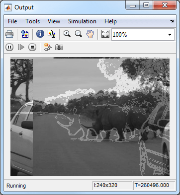
We can see that the edge output is at the right place but the original image is shifted. This output clearly suggests that our first version of Align Video is not robust against a pixel stream that starts in the middle of a frame.
Two reasons explain this behavior. Firstly, EdgeDetector block starts processing only after seeing a valid frame start, indicated by hStart, vStart, and valid going high at the same clock cycle. The block does not output anything for a partial frame. Secondly, the FIFO, inside the Align Video subsystem, starts buffering the frame once the valid signal is true, whether it is a partial frame or a complete frame. Therefore, at the start of the second frame, FIFO has been contaminated with the pixels of the previous partial frame.
Corrected Version of Align Video
Based on the insight gained from the previous section, a revised version of Align Video is shown below.
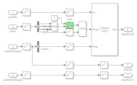
The goal is to only push the pixels of complete frames into the FIFO. If the leading frames are not complete, their valid pixels are ignored.
To achieve this, an enabled register called lock is used (highlighted in the diagram above). Its initial value is logical 0. ANDing this 0 with a delayed version of valid always gives logical 0. This prevents any valid pixels from being pushed into FIFO. The lock toggles its output from logical 0 to 1 only when hStart, vStart, and valid signals assert high, an indicator of the start of a new frame. After lock toggles to 1, the 'push' input of FIFO now follows a delayed version of the valid signal. So the valid pixels of a new frame will be buffered in FIFO.
To test this revised implementation, type the following command at MATLAB prompt.
VERSION=2;
Rerun the simulation. Now the edge output and the original image are perfectly aligned.