Encode and Decode Serial Data Using C2000-based Hardware
This example shows how to use C2000™ Microcontroller Blockset to encode and decode serial data with TI's™ C2000-based hardware.
Introduction
In this example, the Simulink model, performs these actions:
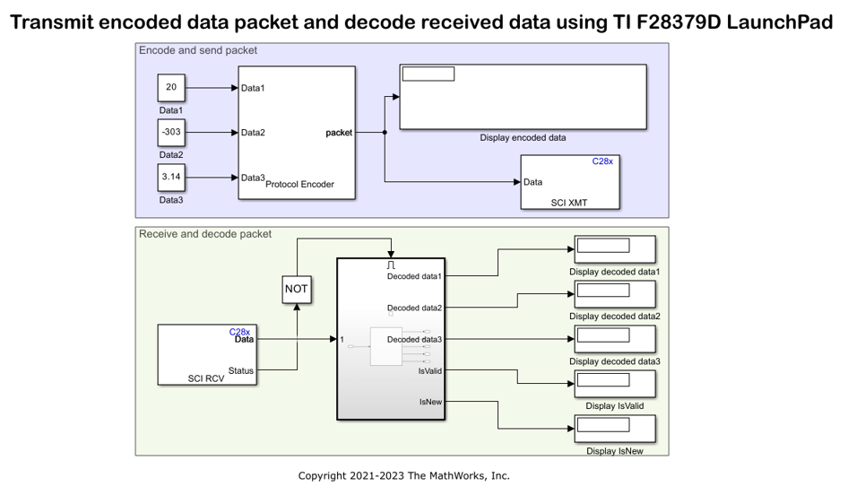
At the transmission end, multiple fields are encoded into packet using Protocol Encoder block and the resulting uint8 byte stream is transmitted using C28x SCI Transmit block.
At the Receiving end, the byte stream is received using C28x SCI Receive block and decoded into individual fields using Protocol Decoder block. The status output of SCI Receive block, which indicates a new data is available, is used to trigger the enabled subsystem containing Protocol Decoder block.
In this model, the Tx pin of SCI Module B sends serial data to the Rx pin of SCI Module B of the TI Delfino F28379D LaunchPad.
This model is configured to run in XCP-based External mode. For more information on External mode, see Signal Monitoring and Parameter Tuning over XCP on Serial.
Open the c2000_encode_decode_packet model.

The model provided in this example is preconfigured for the TI Delfino F28379D LaunchPad. You can run this model on any of the TI boards available under the Hardware board parameter in the Simulink model. For more information on how to change the Hardware board parameter, see the Step 2: Configure the Model for Connected Hardware section of this example.
Required Hardware
To run this example, you must have the following hardware:
Texas Instruments™ Delfino F28379D LaunchPad
Connecting wires
USB cable
Step 1: Connect TX and RX Pins on F28379D Launchpad
1. Connect your TI Delfino F28379D LaunchPad to your computer using the USB cable.
2. Connect the Tx pin of SCI B module (GPIO18 pin) to the Rx pin of SCI B module (GPIO19 pin). This connection is a loopback connection.
Step 2: Configure the Model for Connected Hardware
1. Open the c2000_encode_decode_packet model. This model is configured to run on XCP-based External mode.
2. To configure the model, click Hardware Settings in the Hardware tab of the Simulink® toolbar.
3. In the Configurations Parameters dialog box, select Hardware Implementation.
4. From the Hardware board list, select the TI's C2000-based processor that you are using.
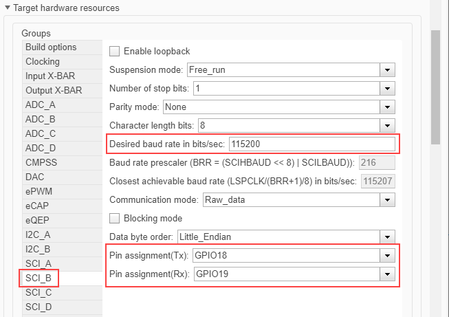
5. Under Target Hardware Resources, click SCI_B tab and configure the properties including baud rate and pin assignments.

If you are using any other GPIO pins for communication, change the Pin assignment parameter value selection accordingly.
6. Click Apply. Click OK to close the dialog box.
Step 3: Configure Blocks in the Simulink Model
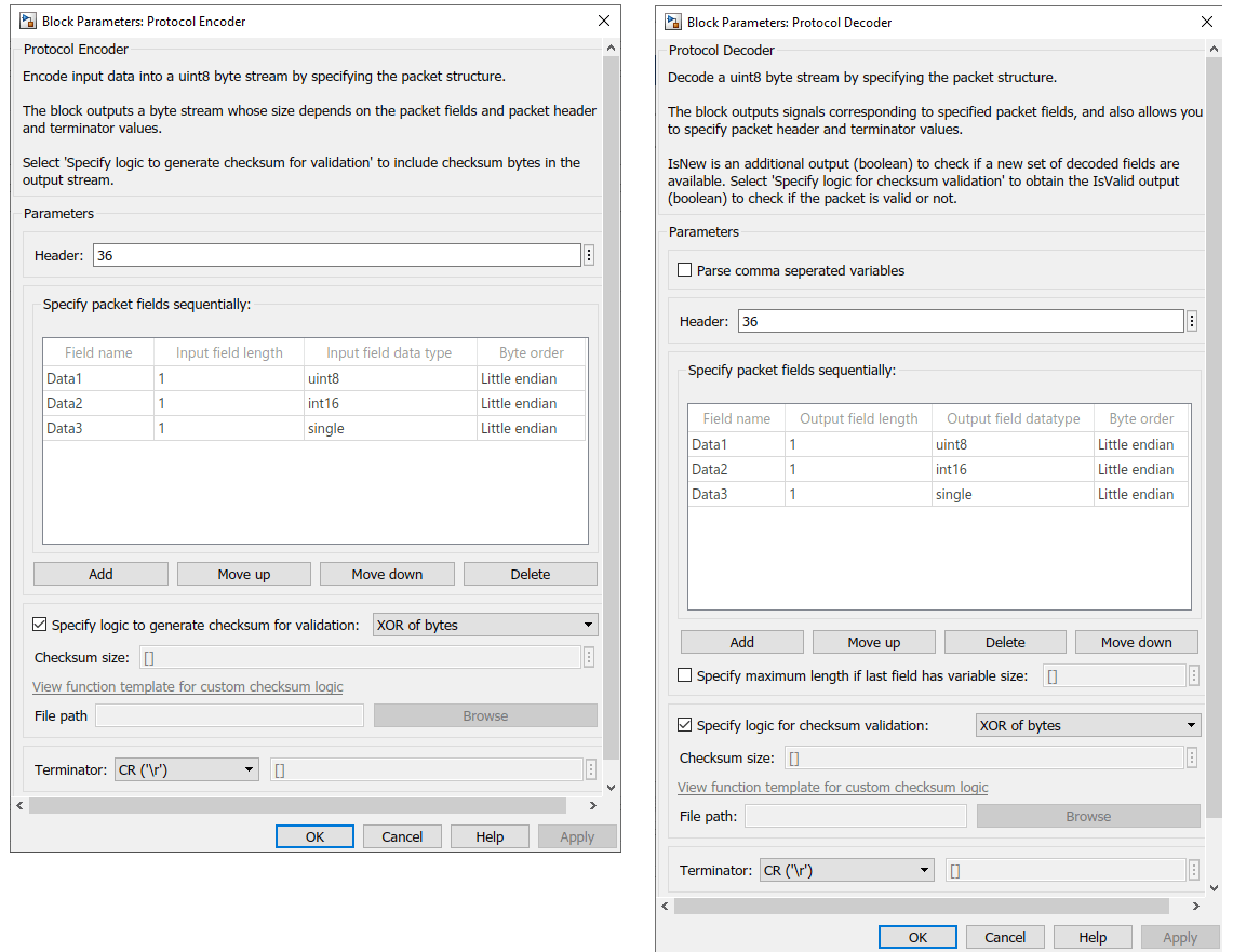
The packet structure used in this example is:

Double-click the blocks and verify the parameter values specified in the Block Parameters dialog box.

For other blocks, the parameters are:
     Block           | Parameter Name                      | Value
    ---------------------------------------------------------------------------------
     Constant        | Interpret vector parameters as 1-D  | selected
                     | Sample time                         | inf
     SCI Transmit    | SCI module                          | B
     SCI Receive     | SCI module                          | B
                     | Data type                           | uint8
                     | Data length                         | 10
                     | Sample time                         | 0.1
     Display Status  | Format                              | short
The value for Data length parameter of SCI Receive block is set to 10, which is the sum of these values:
Header size (1 byte) + Data1 (1 byte) + Data2 (2 bytes) + Data3 (4 bytes) + Checksum (1 byte) + Terminator (1 byte)
Step 4: Run the Model in XCP-based External Mode
You can simulate the model in XCP-based External mode, which deploys the model as a C code on the hardware. The code obtains real-time data from the hardware.
Set Up the Model for XCP-based External Mode
1. To configure the model, click Hardware Settings in the Hardware tab of the Simulink toolbar.
2. In the Configurations Parameters dialog box, select Hardware Implementation.
3. Under Target Hardware Resources, click External mode tab and select XCP on Serial and SCI_A for Communication interface and SCI module parameters respectively. Select the corresponding value for the COM port of the host computer to which the C2000-based processor is connected.

4. Click Apply. Click OK to close the dialog box.
The Stop Time (under Simulation tab) is already set to inf.
Run the Model on XCP-based External Mode
1. To tune parameters and monitor signals in this model while the application runs on the target hardware, on the Hardware tab, click Monitor & Tune.
The lower left corner of the model window displays status while Simulink prepares, downloads, and runs the model on the hardware.
At each time step, data specified in the Constant blocks are encoded into uint8 byte stream (packet) and transmitted by the TX1 pin to the RX1 pin of your C2000-based processor. You can see the uint8 byte stream generated as per the packet structure in the Display encoded data block.
The RX1 pin receives the uint8 byte stream which is decoded using Protocol Decoder block and displays it on the Display Decoded data blocks. Observe the output in the Display Decoded data blocks which will be same as the value given in the Constant blocks at the transmission end.
2. Try changing the values in the Constant blocks connected as input to the Protocol Encoder block, and observe if the same values are getting decoded by the Protocol Decoder block.
3. To stop running the model, click Stop.
Other Things to Try
Try specifying a different packet structure using the block properties and observe the encoded data and decoded data in the
Displayblocks.