C281x Timer
Configure general-purpose timer in Event Manager module
Description
The C281x contains two event-manager (EV) modules. Each module contains two general-purpose (GP) timers. You can use these timers as independent time bases for various applications.
Use the C281x Timer block to set the periodicity of one GP timer and the conditions under which it posts interrupts. Each model can contain up to four C281x Timer blocks.
The C281x Timer module configures GP Timers that other C281 blocks share. For more information and guidance on sharing timers, see Sharing General Purpose Timers Between C281x Peripherals.
Parameters
- Module, Timer no
Select which of four possible timers to configure. Setting Module to
Alets you selectTimer 1orTimer 2in Timer no. Setting Module toBlets you selectTimer 3orTimer 4in Timer no.- Clock source
When Timer no has a value of
Timer 2orTimer 4, use this parameter to select the clock source for the event timer. You can choose eitherInternalorQEP circuit. When you selectInternal, you can configure other options such as Timer period source, Counting mode, and Timer prescaler.- Timer period source
Select the source of the event timer period. Use
Specify via
                dialog
to set the period using Timer period. SelectInput portto create an input, T, that accepts the value of the timer period in clock cycles, from0to65535. Timer period source becomes unavailable when Clock source is set toQEP circuit.- Timer period
Set the length of the timer period in clock cycles. Enter a value from
0to65535. The value defaults to10000.If you know the length of a clock cycle, you can easily calculate how many clock cycles to set for the timer period. The following calculation determines the length of one clock cycle:
In this calculation, you divide the System clock frequency of 150 MHz by the high-speed clock prescaler of 2. Then, you divide the resulting value by the timer control input clock prescaler, 128. The resulting frequency is 0.586 MHz. Thus, one clock cycle is 1/.586 MHz, which is 1.706 µs.
- Compare value source
Select the source of the compare value. Use
Specify via
                dialog
to set the period using the Compare value parameter. SelectInput portto create a block input, W, that accepts the value of the compare value, from0to65535.- Compare value
Enter a constant value for comparison to the running timer value for generating interrupts. Enter a value from
0to65535. The value defaults to5000. The timer only generates interrupts if you enable Post interrupt on compare match.- Counting mode
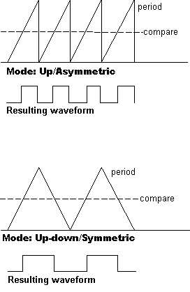
Select
Upto generate an asymmetrical waveform output, orUp-downto generate a symmetrical waveform output, as shown in the following illustration.
When you specify the Counting mode as
Up(asymmetric) the waveform:Starts low
Goes high when the rising period counter value matches the Compare value
Goes low at the end of the period
When you specify the Counting mode as
Up-down(symmetric) the waveform:Starts low
Goes high when the increasing period counter value matches the Compare value
Goes low when the decreasing period counter value matches the Compare value
Counting mode becomes unavailable when Clock source is set to
QEP circuit.- Timer prescaler
Divide the clock input to produce the desired timer counting rate.
Timer prescaler becomes unavailable when Clock source is set to
QEP circuit.- Post interrupt on period match
Generate an interrupt when the value of the timer reaches its maximum value as specified in Timer period.
- Post interrupt on underflow
Generate an interrupt when the value of the timer cycles back to
0.- Post interrupt on overflow
Generate an interrupt when the value of the timer reaches its maximum,
65535. Also set Timer period to65535for this parameter to work.- Post interrupt on compare match
Generate an interrupt when the value of the timer equals Compare value.
References
TMS320x281x DSP Event Manager (EV) Reference Guide, Literature Number: SPRU065, available from the Texas Instruments Web site.