Implement Connected I/O to Communicate with External Peripheral Devices Using Raspberry Pi
This example shows how to implement connected I/O in Normal mode of simulation using Raspberry Pi® hardware. The example also highlights on the advantages of using connected I/O to improve efficiency while prototyping a Simulink® model.
Introduction
Connected I/O gains prominence in Simulink model prototypes because it allows you to communicate with hardware peripherals before you deploy the model on the hardware. This feature not only enables you to modify your model design to meet requirements before deploying it on the hardware, but also helps monitor its immediate effect in real-time, thus, reducing the time required to prototype the model.
This section describes the Simulink Support Package for Raspberry Pi Hardware blocks that support connected I/O in the Normal mode of simulation. The source blocks when used in connected I/O read data from the peripherals connected to the Raspberry Pi board. Similarly, the sink blocks when used in connected I/O write data to the peripherals connected to the Raspberry Pi board.
Source Blocks
Sink Blocks
For more information on how connected I/O works, see Communicate with Hardware Using Connected IO.
Prerequisites
Complete the Get Started with Simulink Support Package for Raspberry Pi Hardware example.
Required Hardware
Raspberry Pi board You can use the input and output hardware peripherals corresponding to the respective source or sink blocks of the Simulink Support Package for Raspberry Pi Hardware that supports connected I/O in Normal mode of simulation. Micro USB cable Connecting wires
Hardware Setup
Connect the Raspberry Pi board to the host computer.
Connect the hardware peripheral device to the Raspberry Pi board.
Simulink Model for Connected I/O
This example uses a preconfigured model from the Simulink Support Package for Raspberry Pi Hardware. In this model, a simple image processing algorithm, for RGB image data, is implemented using a V4L2 Video Capture block (used to capture live video) and the SDL Video Display block (used to display live video). You can manually select the desired image processing operation that you want on the video captured by the camera and display it on the SDL video display screen.
Open the raspberrypi_image_processing Simulink model.

The Image processing algorithm subsystem receives four inputs.
The red component information of the video captured by the camera.
The green component information of the video captured by the camera.
The blue component information of the video captured by the camera.
The manual Control selection output for the desired image processing algorithm to be processed.
a. Option 0: Convert the video to display only the red component
b. Option 1: Convert the video to display only the green component
c. Option 2: Convert the video to display only the blue component
d. Option 3: Convert the video to display only the grey-scale output
e. Option 4: Convert the video to display only the edge-detection output
f. Option 5: Filter median noise

Configure Parameters and Hardware Setup
Configure these parameters in the V4L2 Video Capture block in the Camera output area.
Enter the path and name of the video device in the Device name parameter.
Specify the width in pixels and height in lines of the video that you want to capture in the Image size parameter.
Set the video format in the Pixel format parameter to RGB.
Select the Sample time of the video device.
Configure these parameters in the SDL Video Display block of the Output display area.
Set the Pixel format of the input video stream to RGB.
Configure these parameters in the Constant block in the Manual Control area.
Enter a value in the Constant value parameter to perform the desired image processing operation on the video captured from the camera and display it on the SDL video display screen.
The default value of the Sample time parameter is
inf.
You can either use the USB camera or the on-board camera. In this example, an external USB camera is interfaced with the Raspberry Pi board.
Configure these parameters in the Configuration Parameters dialog box.
Open the Simulink model.
On the Modeling tab, select Model Settings.
In the Configuration Parameters dialog box, select Hardware Implementation.
Set the Hardware board parameter to
Raspberry Pi. This selection populates the Hardware board settings parameters with the default values for the Raspberry Pi hardware.The Communication Interface parameter is set to the
TCP/IPoption.
Run Simulink Model
Enter the image processing operation option number in the Constant value parameter in the Manual Control area.
On the Hardware tab of the Simulink model, in the Mode section, select Connected IO, and then click
Run with IO.Observe the corresponding video output on the SDL video display screen.
While the model is simulating, you can change the option in the Constant value parameter and observe the corresponding output for all the image processing operations from 0 through 5.
SDL Video Display output for Option 0: Display only the red component

SDL Video Display output for Option 1: Display only the green component

SDL Video Display output for Option 2: Display only the blue component
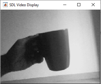
SDL Video Display output for Option 3: Display only the grey-scale output

SDL Video Display output for Option 4: Display only the edge-detection output

SDL Video Display output for Option 5: Filter median noise

Using connected I/O, you can manually select the options from 0 to 5 and observe the corresponding output on the SDL video display screen without deploying the model on the Raspberry Pi hardware. You can also modify the image processing algorithm and observe its effect on the video output.
See Also
Select a Web Site
Choose a web site to get translated content where available and see local events and offers. Based on your location, we recommend that you select: United States.
You can also select a web site from the following list
Americas
- América Latina (Español)
- Canada (English)
- United States (English)
Europe
- Belgium (English)
- Denmark (English)
- Deutschland (Deutsch)
- España (Español)
- Finland (English)
- France (Français)
- Ireland (English)
- Italia (Italiano)
- Luxembourg (English)
- Netherlands (English)
- Norway (English)
- Österreich (Deutsch)
- Portugal (English)
- Sweden (English)
- Switzerland
- United Kingdom (English)