Implement Distributed Control Logic in a Flexible Manufacturing System
This example shows how you can use Stateflow® charts to model a flexible manufacturing system that uses two independently operating pick-and-place robot arms to place balls into cups. The model uses distributed control logic to send commands to and monitor the status of the components.
The example uses Stateflow charts to model:
Reusable, componentized control algorithms for the robots and shuttles
A network layer that communicates with the physical components
Additionally, the example uses Embedded Coder® to generate embedded code from the Stateflow charts, and uses Simulink® 3D Animation™ to animate the model. For the software and hardware requirements for Simulink 3D Animation, see Unreal Engine Simulation Environment Requirements and Limitations (Simulink 3D Animation).
The physical components of the manufacturing system include:
A robot that picks and places cups.
A robot that picks and places balls.
Four shuttles that hold and move objects.
A conveyor belt with five designated shuttle stations.
A slide that leads to a bin for the assembled products.
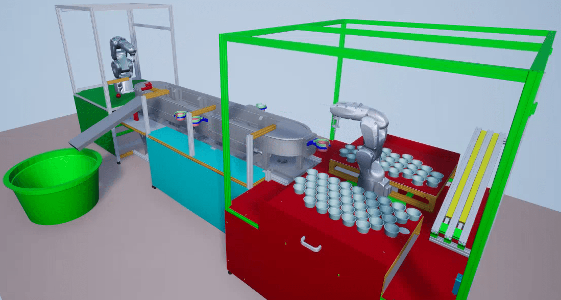
The components operate in this order:
The first robot arm places a cup into a shuttle.
The shuttle moves to the second robot arm.
The second robot arm places a ball inside the cup.
The shuttle moves to the slide.
The shuttle releases the cup.
The cup slides into the bin.
Open Model
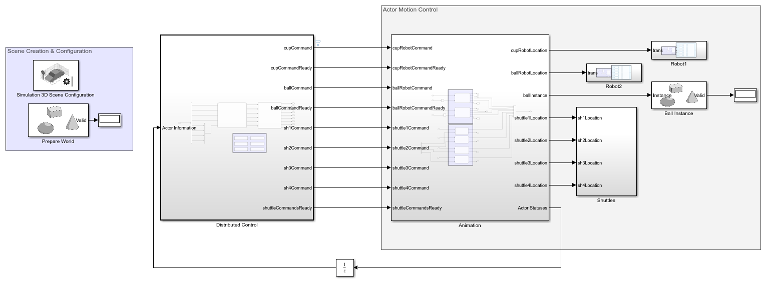
Open the sfManufacturingSystem model. The model contains these subsystems and areas:
The
Distributed Controlsubsystem contains the controllers for each component of the manufacturing system. It also contains a network layer that sends commands to the plant model.The
Actor Motion Controlarea is the plant model. The blocks and subsystems in this area turn commands into animations.The
Scene Creation & Configurationarea initializes the animation settings and components.
In the Distributed Control subsystem, the Network Layer subsystem uses the data store memory flags in the Command Ready Flags area to signal when the plant model reads a command.
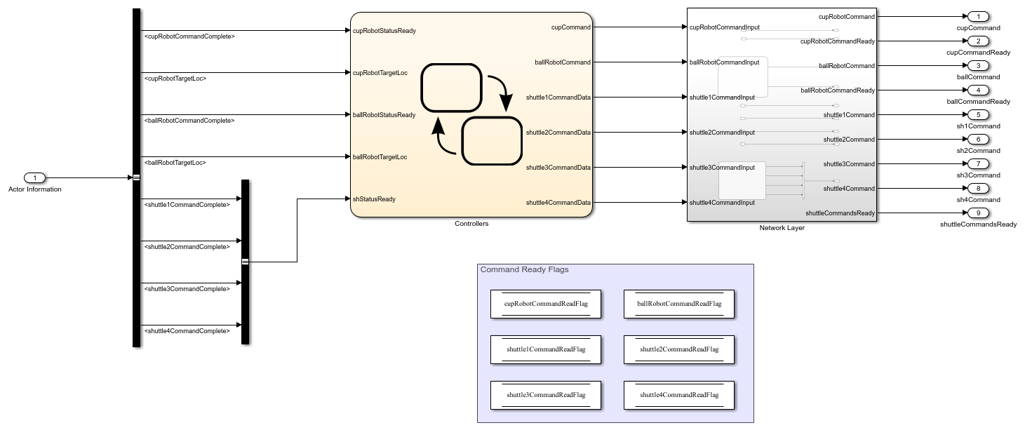
Examine Controllers Chart
The Controllers chart models each shuttle and robot as a separate, masked atomic subchart. The sfRobotAndShuttleLib library contains these subcharts. For more information, see Create Reusable Subcomponents by Using Atomic Subcharts and Reuse Charts in Models by Using Chart Libraries.
Every atomic subchart from the same library chart contains identical states, transitions, and data objects. However, by using mask parameters and mappings, the atomic subcharts initialize their data objects to different values. For more information, see Mask Atomic Subcharts and Boxes in Stateflow.
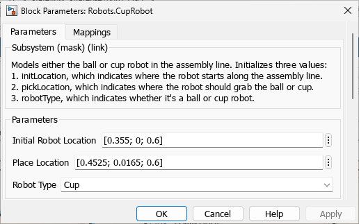
For example, double-click on the CupRobot atomic subchart to open the Block Parameters dialog box.
Double-click on the BallRobot atomic subchart. Observe the differences between the values.
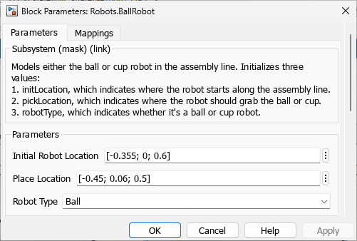
The parameters define different locations, dropoff points, and robot types for each robot. Similarly, each robot has different mappings. In the Block Parameters dialog box, click the Mappings tab.
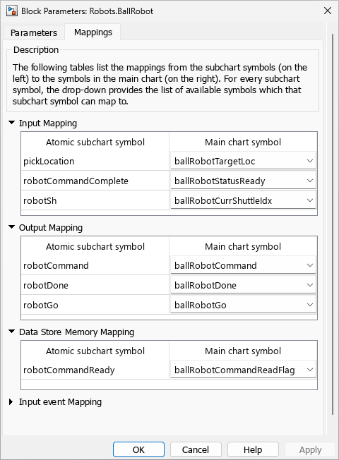
The Mappings tab shows how the symbols in the BallRobot atomic subchart map to the data objects in the Controllers chart. For example, the pickLocation input in BallRobot receives data from the ballRobotTargetLoc object in the Controllers chart. For more information about mapping, see Map Variables for Atomic Subcharts and Boxes.
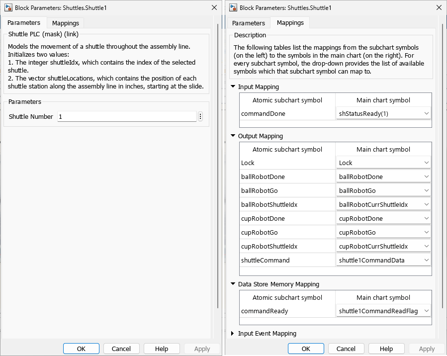
The shuttles also use parameters and mappings to define unique values.
To simulate the simultaneous, independent action of each shuttle and robot, the example models the components as parallel atomic subcharts. Parallel subcharts execute concurrently. In other words, when the Controllers chart is active, every robot and shuttle subchart is also active. For more information, see Define Exclusive and Parallel Modes by Using State Decomposition.
Parallel subcharts execute on the same step, but not simultaneously. To prevent race conditions, parallel subcharts execute in a defined order during each step. The execution order appears in the upper-right corner of each area or subchart.
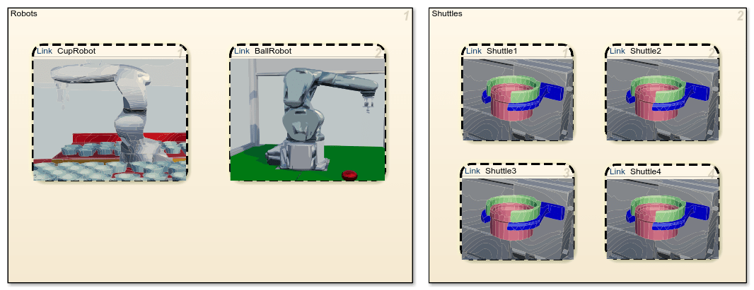
In the Controllers chart, the subcharts in the Robot area execute in the order they appear in the manufacturing system:
CupRobotBallRobot
Afterward, the subcharts in the Shuttles area execute in ascending order:
Shuttle1Shuttle2Shuttle3Shuttle4
Examine Control Logic for Cup and Ball Robots
The robot charts operate in a loop, transitioning along a linear series of states. Each state represents a command. For example, open the CupRobot atomic subchart.
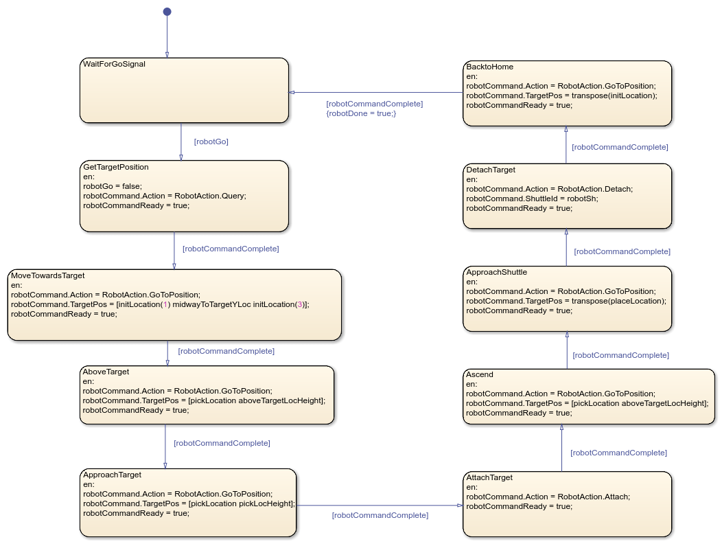
A robot begins the loop by waiting for a shuttle in the WaitForGoSignal state. When a shuttle arrives, robotGo becomes true and the robot transitions to the next state.
At each state in the loop, the robot sends a command to the network layer. When the plant model completes the command, the robot moves to the next state. After the robot completes the full sequence of commands, the subchart sets the robotDone output to true.
The robots send commands using data objects:
The
robotCommandoutput defines what action the robot takes and where the action is performed.The
robotCommandReadydata store specifies whether a command is ready.
The RobotAction enumeration defines the available actions for robotCommand:
Undefined— No command set.GoToPosition— Move the hand of the robot arm.Query— Get the position of the ball or cup.Attach— Grab the ball or cup.Detach— Release the ball or cup.
For example, in the DetachTarget state, the cup robot drops a cup into a shuttle by:
Creating an action to detach the cup.
Setting the shuttle in front of the robot as the destination.
Marking the command as ready.
After sending the command, the cup robot waits for the command to complete. When robotCommandComplete becomes true, the robot transitions to the BacktoHome state.
Examine Conveyor Belt and Shuttle Station Control Logic
To prevent collisions as the shuttles move through the manufacturing system, the Controllers chart models the status of the five shuttle stations by using the Boolean values in the local vector Lock.
Before a shuttle moves, it checks if the destination station is occupied. If the station is unoccupied, the shuttle moves to and locks the station by setting the associated Boolean to true. When the shuttle leaves the station, it resets the Boolean to false.
To improve readability, the enumeration in the ShuttleStations.m file maps each shuttle station in Lock to a name:
CupDropOffMidwayToCupRobotCupRobotMidwayToBallRobotBallRobot
Additionally, the model uses parameters from the data dictionary sfRobotDictionary.sldd to display constants in a readable format. The parameters include:
aboveTargetPickLoc: A scalar that represents the height at which a robot picks up a ball or cup.midwayToTargetYLoc: A scalar that represents the initial offset height of the robot above the target.lastShuttleInQueue: A scalar that represents the ID of the last shuttle to begin moving through the system.shuttleLocations: A vector that represents the coordinates of each shuttle station.
For more information, see Share Parameters with Simulink and the MATLAB Workspace.
Examine Atomic Subcharts for Shuttles
When the manufacturing system initializes, the shuttles queue between the slide and the cup robot. The first robot enters the cup robot station, receives a cup, and leaves. Afterward, the next shuttle takes its place. This process continues until all shuttles leave the starting queue. For example, open the Shuttle1 atomic subchart.
The subchart models the initialization process by using the Init state and the connected transitions. This image shows only the initialization logic in the shuttle subcharts.
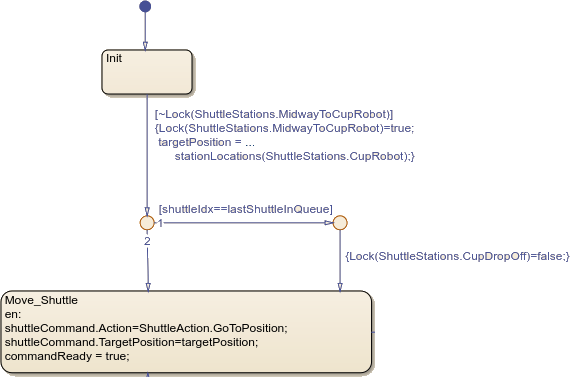
When the model initializes, each shuttle subchart begins in the Init state. The Lock vector, which is shared between subcharts, marks the queuing location, CupDropOff, as occupied.
When the Controllers chart takes a step, every shuttle evaluates the transition from Init to Move_Shuttle, starting with the Shuttle1 subchart. If Shuttle1 detects the MidwayToCupRobot station is unlocked, the shuttle:
Occupies
MidwayToCupRobotSets the target position to
Robot1Transitions to the
Move_Shuttlestate
In the same step, Shuttle2, Shuttle3, Shuttle4 sequentially execute. Each shuttle detects MidwayToCupRobot is occupied and remains in the Init state.
After Shuttle1 enters the Move_Shuttle state, it begins to move through the manufacturing system. When it leaves the MidwayToCupRobot station, Shuttle2 takes its place. The process continues until all the shuttles leave the initial queue. When the final shuttle leaves, it unlocks the CupDropOff station.
After the shuttles initialize, they operate in a loop, moving along the conveyor belt and performing actions.
Similar to the robots, the shuttles use two data objects to send commands:
The
shuttleCommandoutput defines what action the shuttle takes and where the action is performed.The
CommandReadydata store specifies whether a command is ready.
The ShuttleAction enumerations defines the available actions for shuttleCommand:
Undefined— No command set.GoToPosition— Move along the conveyor belt.Unload— Release any held objects.Stop— Stop moving.
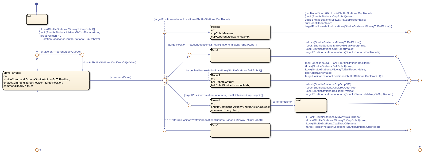
Shuttles start the loop by entering the Move_Shuttle state and executing several actions:
Create a movement command for the shuttle.
Set the position the shuttle will move to.
Inform the network layer the command is ready to execute.
Afterward, the shuttle waits for the command to execute.
When the command executes, the shuttle transitions to one of five paths that represent the shuttle stations. The chart organizes the paths from top-to-bottom according to which station appears first in the manufacturing system. Each path corresponds to different behaviors.
Robot1Path — Move to the cup robot and wait for a cup.Park2Path — Queue in front of the ball robot.Robot2Path — Move to the ball robot and wait for a ball.UnloadPath — Move to the slide and release the ball-in-cup.Park1Path — Queue in front of the cup robot.
After a shuttle completes a path, it returns to the Move_Shuttle state to prepare for the next path.
For example, when a shuttle takes the Unload path, the shuttle performs these actions:
Enter the
Unloadstate.Create an
Unloadcommand to release the ball-and-cup. SetcommandReadytotrue.When
commandDonebecomestrue, transition to theWaitstate.When the
CupDropOffstation becomes available, lock theCupDropOffstation. Unlock theUnloadstation. Set the nexttargetPositiontoRobot1Park.Transition to the
Move_Shuttlestate, which moves the shuttle to the next station.
Simulate the Model
In the Simulation tab, click Run to simulate the model. The model may take time to load and prepare the animation assets.
As the model transitions between the states of the robot and shuttle charts and executes commands, the manufacturing system animates the components.