Distance Relay Protection in AC Microgrid
This example shows how to model a distance relay in an AC microgrid. The relay block comprises impedance relay characteristic and mho relay characteristic. You can use this example to study the performance of impedance relay and mho relay in various fault conditions. Both the relays have two types of relays for ground fault and phase-phase fault.
The impedance relay comprises a directional unit and a blinder unit. The directional unit ensures the tripping in a specified direction, and the blinder unit avoids malfunction of the relay during load encroachment.
AC Microgrid Overview
The figure below shows an AC microgrid with a distance relay and a circuit breaker. The microgrid generates electricity at a voltage level of 11 kV. A three-phase transformer steps down the source voltage to 400 V.
To isolate the faulty section of the transmission line, relay and circuit breaker are connected next to the step-down transformer. An inductive load of 30 kW with a lagging power factor of 0.95 is connected at the receiving end of the transmission line.
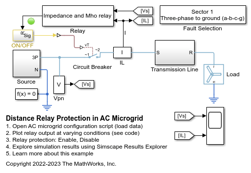
Relay Block Overview
The relay block comprises the two relay characteristics, impedance and mho relay. Relay characteristic has three zones based on the reach of the relay. A Fourier block estimates the fundamental voltage and current signals.
The relay estimates the line impedance from the circuit breaker to the fault points. When the estimated impedance is less than the reach of the first zone, the relay triggers a trip signal without any time delay. If the estimated impedance is less than the reach of the second zone, the relay triggers a trip signal after a finite time delay. When the estimated impedance becomes less than the third zone reach, the relay triggers the trip signal after a time delay which must be greater than the time delay for the second zone.
To avoid tripping in the reverse direction of the fault, the impedance relay consists of a directional unit. You can set the direction of the impedance relay based on your requirements. The impedance relay does not trip if the estimated impedance falls in the blinder region.
This example also implements a mho relay with inherited directional unit. The mho relay uses self polarizing parameter like phase and line voltages.
Plot for Voltage, Current, and Estimated Impedance
The plot below shows the variation of the estimated impedance with respect to time. A single-phase to ground (a-g) fault is initiated in Sector 1 of the transmission line with a fault initiation time of 0.056 sec. To estimate the fundamental component of voltage and current signal, this example uses full cycle Fourier analysis.
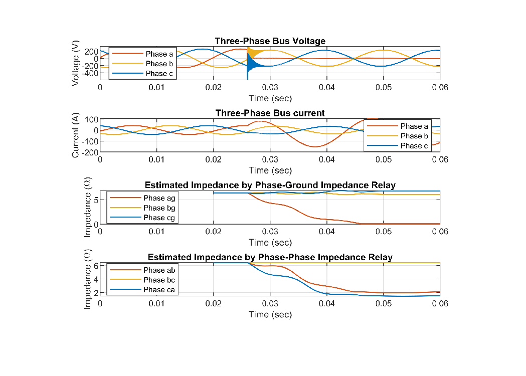
Single-Phase to Ground (a-g) Fault
A single-phase to ground (a-g) fault is initiated in Sector 1 of the transmission line.
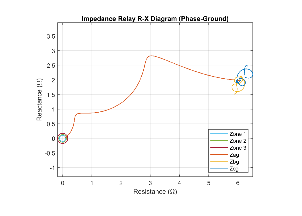
R-X Diagram of Phase-Ground Impedance Relay
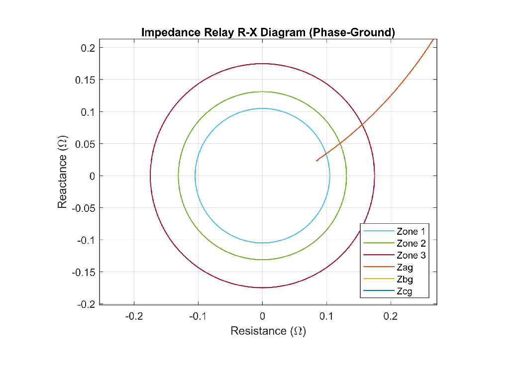
The plot below shows the R-X diagram of the phase-ground Impedance relay. This figure shows that the phase to ground (a-g) impedance decreases and reaches zone 1.
This figure shows the R-X diagram more in detail.
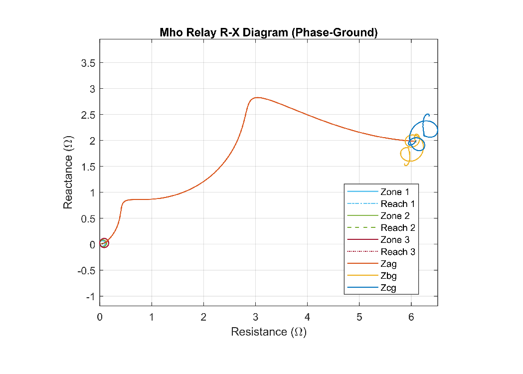
R-X Diagram of Phase-Ground Mho Relay
The plot below shows the R-X diagram of the phase-ground Mho relay. This figure shows that the phase to ground (a-g) impedance decreases and reaches zone 1 of the relay.
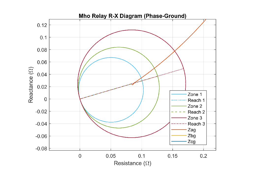
This figure shows the R-X diagram more in detail.
Two-Phase Fault (a-b)
A phase-phase (a-b) fault is initiated in Sector 1 of the transmission line.
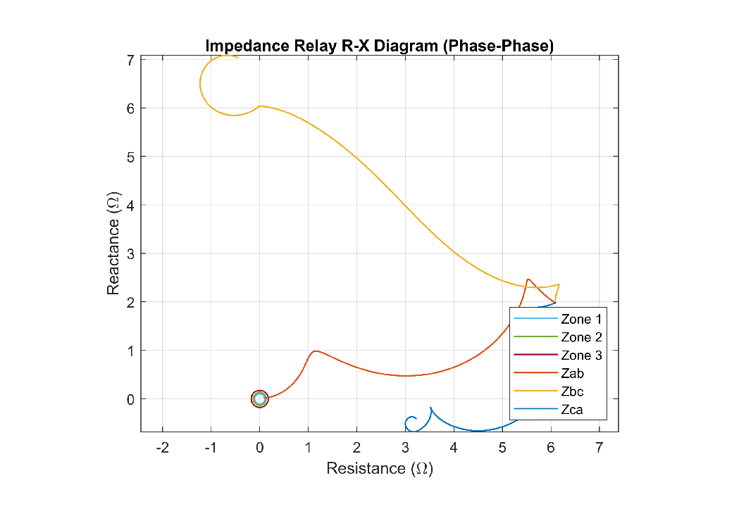
R-X Diagram of Phase-Phase Impedance Relay
The plot below shows the R-X diagram of the phase-phase Impedance relay. This figure shows that the phase-phase impedance (a-b) decreases and reaches zone 1 of the relay.
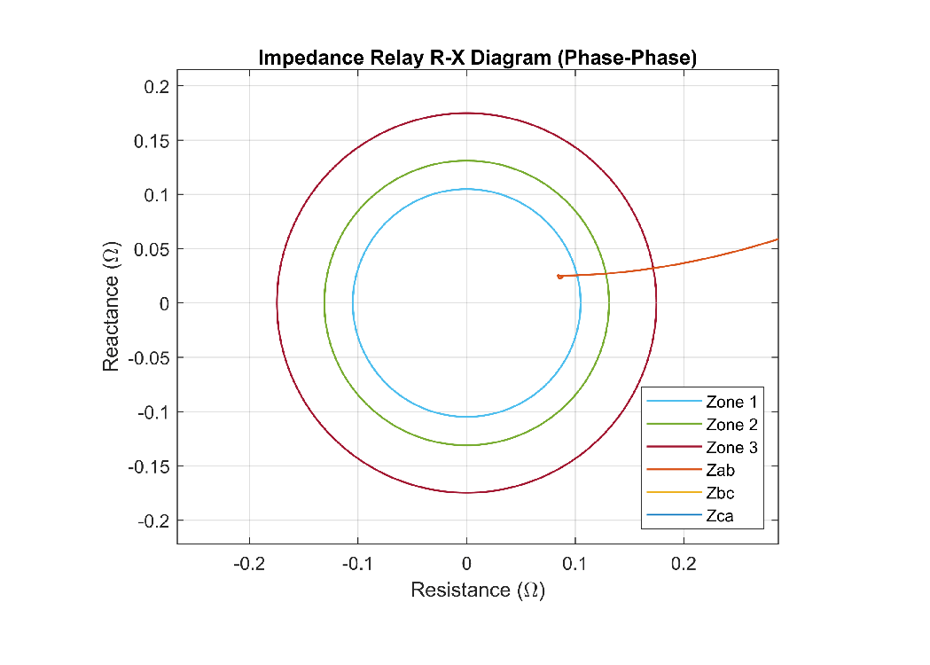
This figure shows the R-X diagram more in detail.
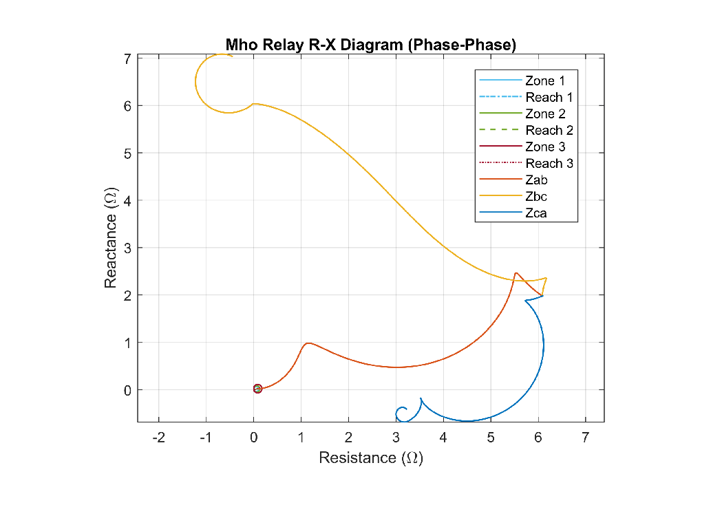
R-X Diagram of Phase-Phase Mho Relay
The plot below shows the R-X diagram of the phase-phase Mho relay. A two-phase to (a-b) fault is initiated in Sector 1 of the transmission line. This figure shows that the phase-phase impedance (a-b) decreases and reaches zone 1 of the relay.
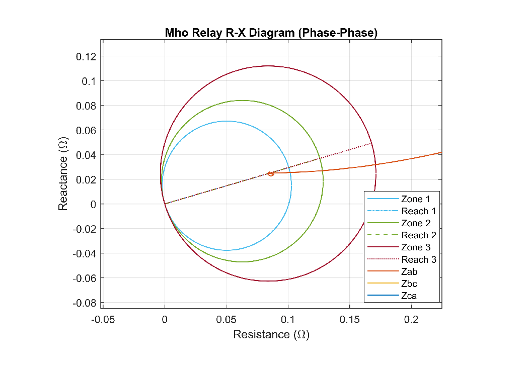
This figure shows the R-X diagram more in detail.
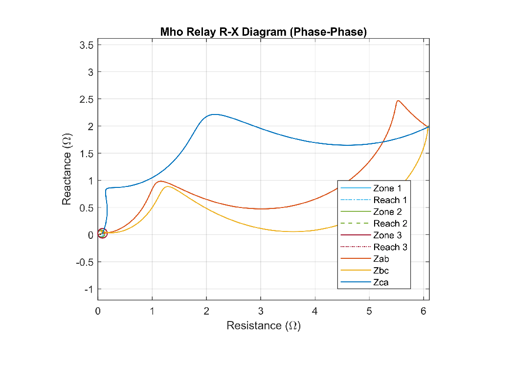
Three-Phase to Ground Fault (a-b-c-g)
A three-phase to ground fault (a-b-c-g) is initiated in Sector 1 of the transmission line. The plot below shows the estimated impedance for three-phase to ground fault on the R-X diagram of the phase-phase Mho relay. This figure shows that the phase-phase estimated impedance decreases and reaches zone 1 of the relay.
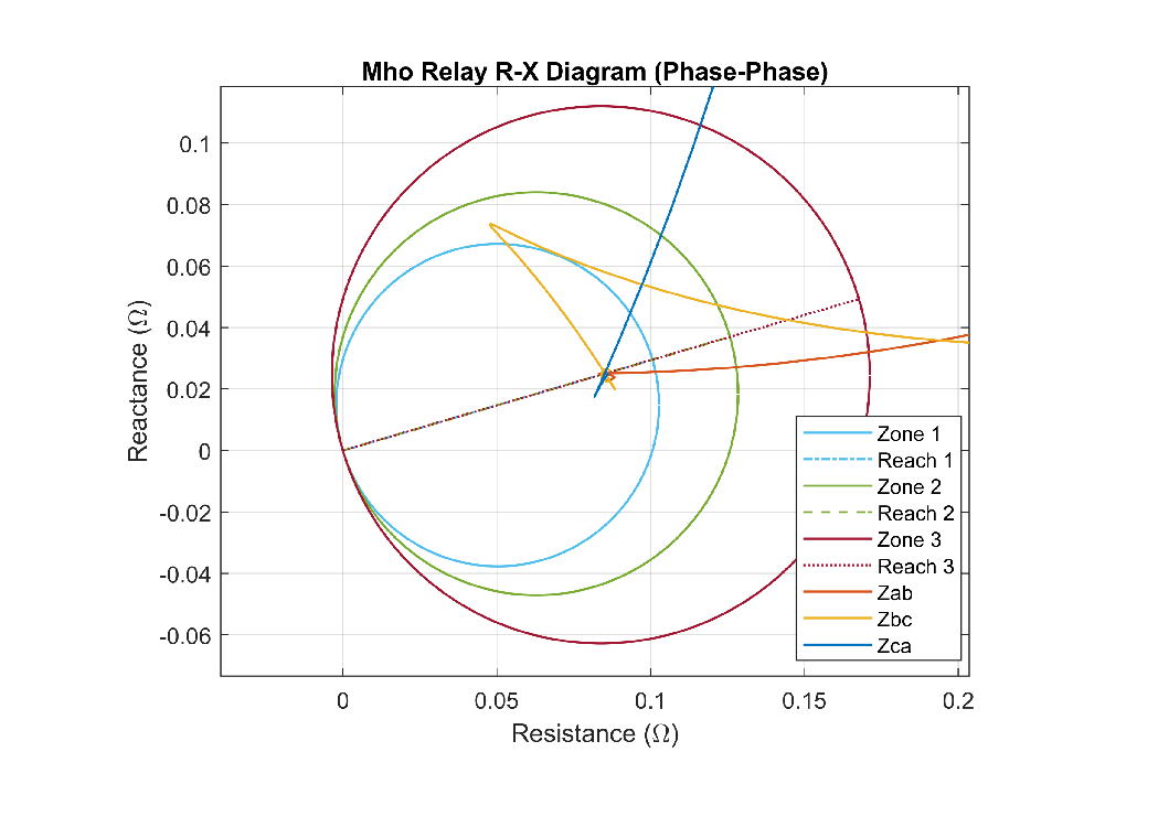
This figure shows the R-X diagram more in detail. You can see the final estimated impedance.
Relay Parameters Configuration Overview
Select the type of relay, Relay selection - Impedance relay, Mho relay, or Impedance & Mho relay.
Fundamental frequency (Hz) - Rated system frequency, in Hz, specified as a scalar. This value must be greater than zero.
Switching time step (s) - Relay Sampling time, in sec, specified as a scalar.
Minimum threshold voltage (V) - Minimum operating threshold voltage, in Volt.
Minimum threshold current (A) - Minimum operating threshold current, in Amp.
Trip duration (s) - Time duration for the trip signal, in sec.
Compensation factor (k0) - Compensation factor for a ground fault.
Time delay zone2 (s) - Relay trip signal delay time for the second zone, in sec.
Time delay zone3 (s) - Relay trip signal delay time for the third zone, in sec.
Zone 1 reach (ohm) - Mho relay reach for the first zone, in Ohm.
Zone 2 reach (ohm) - Mho relay reach for the second zone, in Ohm.
Zone 3 reach (ohm) - Mho relay reach for the third zone, in Ohm.
Zone 1 reach (ohm) - Impedance relay reach for the first zone, in Ohm.
Zone 2 reach (ohm) - Impedance relay reach for the second zone, in Ohm.
Zone 3 reach (ohm) - Impedance relay reach for the third zone, in Ohm.
Blinder reach (ohm) - Minimum blinder reach, in Ohm.
Blinder angle (deg) - Blinder angle limit, in degree. The relay does not trip if the impedance angle is between +Blinder angle and -Blinder angle and the impedance magnitude is greater than the Blinder reach.
Directional unit minimum angle (deg) - Minimum angle for directional unit, in degree.
Directional unit maximum angle (deg) - Maximum angle for directional unit, in degree. The impedance relay trips only if the estimated impedance angle is greater than the Directional unit minimum angle and less than the Directional unit maximum angle.
Fault Parameters Configuration Overview
Fault location - Fault-point.
Fault type - Fault type in the transmission line such as single-phase to ground, two phase, two-phase to ground, three-phase and three-phase to ground fault.
Faulted phase-neutral resistance (ohm) - Resistance between phase and neutral, in Ohm.
Faulted neutral-ground resistance (ohm) - Resistance between neutral and ground, in Ohm.
Fault start time (ms) - Fault initiation time, in msec.
Fault duration (ms) - Fault duration, in msec.