Model Start-Up Control Strategy for Wound-Rotor Induction Motor
This example shows how to design a start-up control strategy with a resistor for a wound-rotor induction model using a Simscape™ Electrical™ FEM-Parameterized Induction Machine (Wound Rotor) block.
Model Overview
Open the model to view the circuit.
modelName = "InductionMachineWoundRotorStartUp";
InductionMachineWoundRotorStartUpInit;
open_system(modelName);
The FEM-Parameterized Induction Machine (Wound Rotor) block connects to a three-phase voltage source. This voltage source provides electrical power to the machine in the form of a balanced 460 V three-phase voltage at 60 Hz. A switch connects in series between the voltage source and the machine stator to control the operation. The machine stator end connects to a Floating Neutral (Three-Phase) block, which means that end has a wye configuration with a nearly infinite impedance for the neutral-to-ground path. The rotor terminals connect in series with a resistor bank. The mechanical load consists of a Machine Inertia block and a controlled torque source specifying the load value as a function of time.

The Resistor bank subsystem consists of three sets of three-phase RLC branches with resistances R1, R2, and R3 connected in series. Each node connects to a switch. The control signal vector SR123 turns each switch on or off to increase or decrease the overall equivalent impedance of the resistor bank respectively, which modifies the equivalent rotor resistance in the motor. This can help the motor start-up process, as the rotor resistance directly influences the motor torque-speed characteristics.

The control strategy consists of decreasing the rotor resistance as the rotor speed increases from zero to the rated value of 1 per-unit (p.u.). Logical operations compare the rotor speed p.u. value with 50%, 70%, and 90% thresholds to trigger switching events in the resistor bank that disconnect sections of the resistance banks sequentially.
You can use other control strategies and modify this algorithm to improve the design.

Plot Machine Torque-Speed Characteristics
Simulate the start-up process.
sim(modelName);

Compare the theoretical and actual torque-speed curves for different rotor resistance values.
InductionMachineWoundRotorStartUpPlotCharacteristics
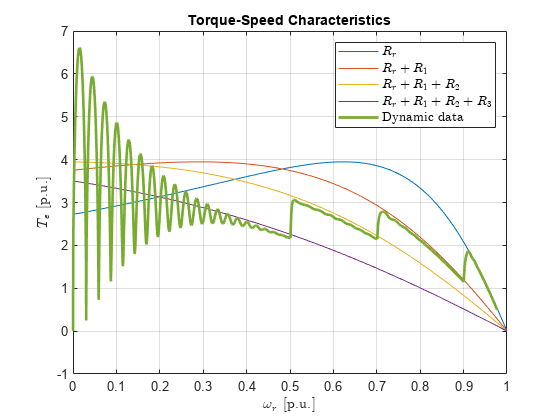
![Figure InductionMachineWoundRotorStartUp/TorqueSpeedCharacteristics contains an axes object. The axes object with title Torque-Speed Characteristics, xlabel $ omega indexOf r baseline $ [p.u.], ylabel $T indexOf e baseline $ [p.u.] contains 5 objects of type line. These objects represent $R_r$, $R_r+R_1$, $R_r+R_1+R_2$, $R_r+R_1+R_2+R_3$, Dynamic data.](../../examples/simscapeelectrical/win64/InductionMachineWoundRotorStartUpExample_06.png)
The torque-speed characteristics change significantly for different rotor resistance values. The control strategy ensures a higher start-up torque and then switches to more effective torque-speed curves as the rotor speed increases.
See Also
FEM-Parameterized Induction Machine (Wound Rotor) | FEM-Parameterized Induction Machine (Squirrel Cage)