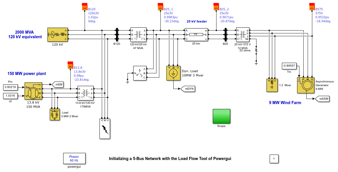
Initializing a 5-Bus Network with the Load Flow Tool of Powergui
This example shows the use of the Load Flow tool of Powergui to initialize a simple 5-bus network consisting of a wind farm connected to a 25-kV distribution feeder and exporting power to a 120 kV network.
G. Sybille (Hydro-Quebec)

Description
The model shows a 9 MW wind farm using asynchronous generators and exporting power to a 120 kV network through a 25-kV distribution feeder. The 120 kV network is modeled by a simple inductive voltage source (short circuit power of 1200 MVA) using the Three-Phase Source block. A 150 MW power plant using a 13.8 kV synchronous generator is connected at the 120 kV bus through a 13.8 kV/ 120 kV transformer.
Simulation
The five Load Flow Bus blocks are used to specify the bus base voltages and to specify the voltage at PV bus and the voltage and angle of the swing bus.
The Load flow parameters are defined in the Load Flow tab of the Synchronous and Asynchronous machine blocks, Three-Phase Source block, Three-Phase Dynamic Load block, and the Three-Phase RLC Load blocks.
Press the 'Apply' button to apply the load flow solution to the model in order to start the simulation in steady-state. Note that the Load flow Bus block displays the bus voltage magnitude and phase angle as block annotations.
Press the 'Report' button to get a report that shows a load flow summary and detailed load flow results at each bus.
Finally, start simulation and check that it starts in steady state.
