Digital Potentiometer Parameterized from Datasheet
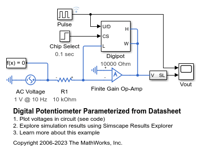
This model shows how to model a digital potentiometer such as is used to control audio amplifiers from a digital circuit or microprocessor-controlled system. The model also shows how you can create your own custom blocks in order to extend the Simscape™ Electrical™ library.
The datasheet specifies an end-to-end resistance R of 10K ohms and a quantization of 16 steps. To look under the Digipot masked subsystem, select the block and type Ctrl-U. The low (L) to wiper (W) resistance is R*N/16, and high (H) to wiper resistance is R*(16-N)/16 where N is the value of an internal counter. The internal counter is enabled by the chip-select (CS) pin, and counts each time the up/down (U/D) pin goes high. The direction of the stepping (up or down) is set by the state of input U/D when digipot is first enabled by the chip select input CS.
In this circuit, the op-amp gain is set by R2/R1 where R2 is the Digipot block resistance. R1 is set to 10K and R2 starts at 10K*8/16 = 5K. Hence the initial gain is 0.5, and the output voltage amplitude is 0.5 volts for a 1 volt peak input sinewave. The Pulse Generator increases the counter N by 1 every second, and the op-amp gain tends to 1 as N approaches 16.
The Digipot block has been implemented as a masked subsystem, and as such is suitable for re-use in other models. Use of triggered and enabled Simulink® subsystems is used to implement the asynchronous counter. To support asynchronous operation, the discrete-time integrator's sample time is set to -1.
Sometimes digipots will only change their resistance when the wiper current is zero. For example, in audio applications this helps prevent audible clicks when the state changes. To implement this, another edge-triggered block can be added after the Pulse Counter block, its trigger signal being driven by a wiper current measurement. Another possible enhancement is to model the wiper resistance by adding a resistor between the wiper port W and the junction between the two variable resistors.
Model

Digipot Subsystem

Simulation Results from Simscape Logging
The plot below shows the input and output voltages of an amplifier whose gain is controlled by a digital potentiometer. The gain is adjusted on the rising edges of the pulses applied to the digital potentiometer.

Results from Real-Time Simulation
This example has been tested on a Speedgoat Performance real-time target machine with an Intel® 3.5 GHz i7 multi-core CPU. This model can run in real time with a step size of 40 microseconds.